Lincoln Aviator: Body Repairs - General Information / Description and Operation - Impact of Insufficient Repair Quality
Body repairs usually require a significant level of intervention in the existing body shell structure. The corrosion protection, seals and NVH components are destroyed and must be replaced.
To prevent the vehicle quality from being compromised due to a poor quality repair, all repairs must be inspected during and after the accident repair.
NOTE: Logs of the acceptance of individual operations are a useful tool for quality assurance. A comprehensive final inspection should be carried out.
In the process, the entire repair sequence must be split into meaningful sections, with the creation of check points to which particular attention must be paid.
The following are some recommended checkpoints sequences:
- During and after body work.
- Final assembly, ancillary components, functional tests.
- Vehicle delivery.
After completion of the body repairs, the following areas should be checked:
- Inspection for functionality of mechanical and electrical components.
- Vehicle must be restored to pre-accident manufacturers design condition.
- Check fit of all body panels, weld and screw connections
- Check fit of ancillary components such as doors and hood.
- Inspect the integrity of all bonded/riveted seams.
- Inspect the quality of welded seams.
- Check seals, plugs and NVH components.
- Corrosion protection must be restored to pre-accident level.
- Check that the vehicle is in correct condition for painting.
After final assembly, a visual inspection and functional inspection is required.
- Check repair area for flaws in paint or incorrect fit of body panels.
- Check installation of all trim components for gaps, rattles or poor alignment and fit.
- Check operation of mechanical components such as door glass and seat operation.
- Check operation of electrical components such as roof opening panel, door locks and audio systems.
- Check for air or water leaks in repaired area.
To ensure a quality repair, perform a pre-delivery vehicle inspection.
- Check corrosion protection, sound damping matting and rubber seals.
- Check paint for overspray, runs, drips and sags.
- Check the cleanliness of the vehicle.
- Perform functional check of the mechanical and electrical components.
- Road test the vehicle.
- Check for squeaks and rattles.
- Check for wind noises and water leaks.
 Description and Operation - Complete Panel Replacement/Partial Replacement
Partial Replacement
Item
Description
1
Sectioning area
2
Manufacture weld joint
Decision Criteria
The following points a crucial to the decision of complete or partial replacement of the part(s)...
 Description and Operation - Plastic Repairs
Plastic Components
NOTE:
Left hand side shown, right hand side similar.
The
following illustration is not all-inclusive of trim levels available...
Other information:
Lincoln Aviator 2020-2025 Service Manual: General Procedures - Fuel System Pressure Check
Special Tool(s) / General Equipment 310-D009 (D95L-7211-A) Fuel Pressure Test Kit Check NOTE: This Fuel System Pressure Check is for the low pressure side of the system. Release the fuel system pressure. Refer to: Fuel System Pressure Release (310-00A Fuel System - General Information - 3...
Lincoln Aviator 2020-2025 Owners Manual: Front Parking Aid
WARNING: The system may not detect objects with surfaces that absorb reflection. Always drive with due care and attention. Failure to take care may result in a crash. WARNING: The system may not detect small or moving objects, particularly those close to the ground...
Categories
- Manuals Home
- Lincoln Aviator Owners Manual
- Lincoln Aviator Service Manual
- Opening and Closing the Hood
- Interior Lamps
- Anti-Theft Alarm
- New on site
- Most important about car
Remote Control
Passive Key

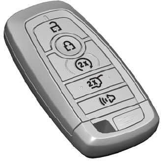
The passive key operates the power locks and the remote start system. The passive key must be in your vehicle to use the push button start.
Note: You may not be able to shift out of park (P) unless the passive key is inside your vehicle.
