
Lincoln Aviator 2020-2026 Service Manual / Body and Paint / Body and Paint / Body Repairs - General Information
Lincoln Aviator: Body and Paint / Body Repairs - General Information
- Specifications
- Description and Operation - Complete Panel Replacement/Partial Replacement
- Description and Operation - Impact of Insufficient Repair Quality
- Description and Operation - Plastic Repairs
- Description and Operation - Sealer, Underbody Protection Material and Adhesives
- General Procedures - Corrosion Prevention
- General Procedures - Joining Techniques
- General Procedures - Plastic Repairs
- General Procedures - Welding Precautions
 Removal and Installation - Side Curtain Airbag
Removal
WARNING:
The following procedure prescribes critical repair steps
required for correct restraint system operation during a crash. Follow
all notes and steps carefully...
 Specifications
General Specifications
Item
Specification
Plug Weld hole
8 mm (0.315 in)
Weld Wire ER70S-3
0...
Other information:
Lincoln Aviator 2020-2026 Owners Manual: Age
WARNING: Tires degrade over time depending on many factors such as weather, storage conditions, and conditions of use (load, speed, inflation pressure) the tires experience throughout their lives. In general, tires should be replaced after six years regardless of tread wear...
Lincoln Aviator 2020-2026 Owners Manual: USB and Bluetooth Audio
..
Categories
- Manuals Home
- Lincoln Aviator Owners Manual
- Lincoln Aviator Service Manual
- Wireless Accessory Charger (If Equipped)
- Description and Operation - Jacking and Lifting
- Keyless Entry
- New on site
- Most important about car
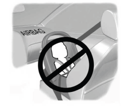
Children and Airbags
WARNING: Airbags can kill or injure a child in a child restraint. Never place a rear-facing child restraint in front of an active airbag. If you must use a forward-facing child restraint in the front seat, move the seat upon which the child restraint is installed all the way back.

Copyright © 2026 www.liaviator2.com