Lincoln Aviator 2020-2025 Service Manual / Powertrain / Engine / Starting System - 3.0L EcoBoost / Description and Operation - Starting System - System Operation and Component Description

Lincoln Aviator: Starting System - 3.0L EcoBoost / Description and Operation - Starting System - System Operation and Component Description

System Operation

System Diagram


Item Description
1 PCM
2 Starter relay
3 Starter motor
4 BCM
5 Automatic transmission
6 Ignition switch

Network Message Chart

  Module Network Input Messages Powertrain Control Module (PCM)


Broadcast Message Originating Module Message Purpose
Ignition status   BCM Provides the PCM with ignition mode.

Starting System

The BCM controls the ignition modes and, in conjunction with the PCM, the starting system.

During a start event, when the ignition switch is turned to Start (without push button start) or the engine start/stop switch and the brake pedal are pressed simultaneously (with push-button start), the PCM and BCM receive a request to start the engine. The PCM recognizes the correct inputs from the BCM and TR sensor and provides voltage and ground to energize the starter relay coil and close the starter relay contacts. The starter relay contacts close, providing voltage to the starter solenoid, allowing the starter motor to crank the engine. The PCM disengages the starter motor once an engine RPM threshold is reached, a set crank time is exceeded or the ignition switch is turned to off (without push button start) or the start/stop button is pressed (with push-button start).

Passive Anti-theft System (PATS)

This vehicle may be equipped with PATS. PATS disables the engine from starting if an unprogrammed PATS key is used or an invalid PCM ID is received. The PATS is controlled by the BCM. If there is a PATS concern that disables the engine, the IPC displays a corresponding message in the message center.
Refer to: Passive Anti-Theft System (PATS) - System Operation and Component Description (419-01B Passive Anti-Theft System (PATS), Description and Operation).
(without Push Button Start) or Refer to: Passive Anti-Theft System (PATS) - System Operation and Component Description (419-01B Passive Anti-Theft System (PATS), Description and Operation).
(with Push Button Start)

Remote Start

The remote start system is controlled by the RKE system. For more information,
Refer to: Handles, Locks, Latches and Entry Systems - System Operation and Component Description (501-14 Handles, Locks, Latches and Entry Systems, Description and Operation).

Component Description

Body Control Module (BCM)


Refer to: Module Controlled Functions - Component Location (419-10 Multifunction Electronic Modules, Description and Operation).

Ignition Switch (without Push Button Start)


Refer to: Steering Wheel and Column Electrical Components - System Operation and Component Description (211-05 Steering Wheel and Column Electrical Components, Description and Operation).

Ignition Switch - Push Button Start (with Push Button Start)

The ignition switch - push button start (engine start/stop button) is a momentary contact switch that is hardwired to the BCM and the PCM. The ignition switch - push button start is used to obtain the OFF, ON or START ignition modes. For more information,
Refer to: Steering Wheel and Column Electrical Components - System Operation and Component Description (211-05 Steering Wheel and Column Electrical Components, Description and Operation).

Integrated Keyhead Transmitter (IKT) (without Push Button Start)


Refer to: Passive Anti-Theft System (PATS) - System Operation and Component Description (419-01B Passive Anti-Theft System (PATS), Description and Operation).

Passive Key (with Push Button Start)


Refer to: Passive Anti-Theft System (PATS) - System Operation and Component Description (419-01B Passive Anti-Theft System (PATS), Description and Operation).

Passive Anti-Theft Transceiver


Refer to: Passive Anti-Theft System (PATS) - System Operation and Component Description (419-01B Passive Anti-Theft System (PATS), Description and Operation).

Powertrain Control Module (PCM)

The PCM provides power and ground to the starter relay to initiate cranking of the engine.

RTM


Refer to: Handles, Locks, Latches and Entry Systems - System Operation and Component Description (501-14 Handles, Locks, Latches and Entry Systems, Description and Operation).

    Description and Operation - Starting System - Overview

    Starting System The starting system controls the cranking of the engine. The PCM energizes the starter relay when it receives inputs from the ignition switch, automatic transmission, and the BCM...

    Diagnosis and Testing - Starting System - 3.0L EcoBoost

    Diagnostic Trouble Code (DTC) Chart Diagnostics in this manual assume a certain skill level and knowledge of Ford-specific diagnostic practices.REFER to: Diagnostic Methods (100-00 General Information, Description and Operation)...

    Other information:

    Lincoln Aviator 2020-2025 Service Manual: Removal and Installation - Cowl Panel


    Removal NOTE: Removal steps in this procedure may contain installation details. Remove the wiper linkage assembly. Refer to: Wiper Linkage Assembly (501-16 Wipers and Washers, Removal and Installation). Remove the bolt and position the wire connectors aside...

    Lincoln Aviator 2020-2025 Service Manual: Diagnosis and Testing - Instrumentation, Message Center and Warning Chimes


    Diagnostic Trouble Code (DTC) Chart Diagnostics in this manual assume a certain skill level and knowledge of Ford-specific diagnostic practices. REFER to: Diagnostic Methods (100-00 General Information, Description and Operation).   Diagnostic Trouble Code Chart Module   DTC Description Action   ABS C0049:01 Brake Fluid Level:General Electrical Failure   GO to Pinpoint Test L   ABS C0049:7B Brake Fluid Level:Low Fluid Level   GO to Pinpoint Test L   IPC P0460:11 Fuel Level Sensor "A" Circuit:Circuit Short To Ground   GO to Pinpoint Test D   IPC P0460:13 Fuel Level Sensor "A" Circuit:Circuit Open   GO to Pinpoint Test D   IPC U0100:00 Lost Communication With ECM/PCM "A":No Sub Type Information   GO to Pinpoint Test CC   IPC U0103:00 Lost Communication With Gear Shift Control Module A:No Sub Type Information   GO to Pinpoint Test CE   IPC U0111:00 Lost Communication With Battery Energy Control Module "A":No Sub Type Information   GO to Pinpoint Test CF   IPC U0121:00 Lost Communication With Anti-Lock Brake System (ABS) Control Module: No Sub Type Information   GO to Pinpoint Test CG   IPC U013F:00 Lost Communication With Pedestrian Alert Control Module:No Sub Type Information   GO to Pinpoint Test CI   IPC U0140:00 Lost Communication With Body Control Module: No Sub Type Information   GO to Pinpoint Test CJ   IPC U0151:00 Lost Communication With Restraints Control Module: No Sub Type Information   GO to Pinpoint Test CM   IPC U0158:00 Lost Communication With Head Up Display:No Sub Type Information   GO to Pinpoint Test CN   IPC U0159:00 Lost Communication With Parking Assist Control Module "A": No Sub Type Information   GO to Pinpoint Test CP   IPC U0193:00 Lost Communication With "Digital Audio Control Module A": No Sub Type Information   GO to Pinpoint Test CQ   IPC U0199:00 Lost Communication With "Door Control Module A":No Sub Type Information   GO to Pinpoint Test CR   IPC U0212:00 Lost Communication With Steering Column Control Module: No Sub Type Information   GO to Pinpoint Test CS   IPC U0212:82 Lost Communication With Steering Column Control Module:Alive/Sequence Counter Incorrect/Not Updated   GO to Pinpoint Test CS   IPC U0232:00 Lost Communication With Side Obstacle Detection Control Module - Left: No Sub Type Information   GO to Pinpoint Test CU   IPC U0233:00 Lost Communication With Side Obstacle Detection Control Module - Right: No Sub Type Information   GO to Pinpoint Test CU   IPC U023A:00 Lost Communication With Image Processing Module A: No Sub Type Information   GO to Pinpoint Test CW   IPC U023B:82 Lost Communication With Image Processing Module B:Alive/Sequence Counter Incorrect/Not Updated   GO to Pinpoint Test CX   IPC U0241:00 Lost Communication With Headlamp Control Module "A":No Sub Type Information   GO to Pinpoint Test CY   IPC U0253:00 Lost Communication With Accessory Protocol Interface Module:No Sub Type Information   GO to Pinpoint Test CZ   IPC U0260:00 Lost Communication With Seat Control Switch Module "A":No Sub Type Information   GO to Pinpoint Test DA   IPC U0293:00 Lost Communication with Hybrid/EV Powertrain Control Module:No Sub Type Information   GO to Pinpoint Test CD   IPC U0293:82 Lost Communication with Hybrid/EV Powertrain Control Module:Alive/Sequence Counter Incorrect/Not Updated   GO to Pinpoint Test CD   IPC U0401:00 Invalid Data Received from ECM/PCM A:No Sub Type Information   GO to Pinpoint Test CC   IPC U0401:81 Invalid Data Received from ECM/PCM A:Invalid Serial Data Received   GO to Pinpoint Test CC   IPC U0401:82 Invalid Data Received from ECM/PCM A:Alive/Sequence Counter Incorrect/Not Updated   GO to Pinpoint Test CC   IPC U0401:86 Invalid Data Received from ECM/PCM A:Signal Invalid   GO to Pinpoint Test CC   IPC U0405:56 Invalid Data Received From Cruise Control Module:Invalid/Incompatible Configuration   GO to Pinpoint Test CK   IPC U0412:86 Invalid Data Received From Battery Energy Control Module "A":Signal Invalid   GO to Pinpoint Test CF   IPC U0415:00 Invalid Data Received From Anti-Lock Brake System (ABS) Module: No Sub Type Information   GO to Pinpoint Test CG   IPC U0415:82 Invalid Data Received from Anti-Lock Brake System (ABS) Control Module "A":Alive/Sequence Counter Incorrect/Not Updated   GO to Pinpoint Test CG   IPC U0420:82 Invalid Data Received from Power Steering Control Module "A":Alive/Sequence Counter Incorrect/Not Updated   GO to Pinpoint Test CH   IPC U0422:00 Invalid Data Received From Body Control Module:No Sub Type Information   GO to Pinpoint Test CJ   IPC U0424:80 Invalid Data Received From HVAC Control Module:ISO/SAE Reserved   GO to Pinpoint Test CL   IPC U0424:81 Invalid Data Received From HVAC Control Module:Invalid Serial Data Received   GO to Pinpoint Test CL   IPC U0424:82 Invalid Data Received From HVAC Control Module:Alive/Sequence Counter Incorrect/Not Updated   GO to Pinpoint Test CL   IPC U0431:82 Invalid Data Received From Body Control Module "A":Alive/Sequence Counter Incorrect/Not Updated   GO to Pinpoint Test CJ   IPC U0452:81 Invalid Data Received From Restraints Control Module:Invalid Serial Data Received   GO to Pinpoint Test CM   IPC U045A:82 Invalid Data Received From Parking Assist Control Module "A":Alive/Sequence Counter Incorrect/Not Updated   GO to Pinpoint Test CP   IPC U049C:82 Invalid Data Received From Battery Charger Control Module "A":Alive/Sequence Counter Incorrect/Not Updated   GO to Pinpoint Test CO   IPC U0531:82 Invalid Data Received From Rear Gate Module:Alive/Sequence Counter Incorrect/Not Updated   GO to Pinpoint Test CT   IPC U0533:00 Invalid Data Received From Side Obstacle Detection Control Module-Left: No Sub Type information   GO to Pinpoint Test CU   IPC U0533:56 Invalid Data Received From Side Obstacle Detection Control Module "A":Invalid/Incompatible Configuration   GO to Pinpoint Test CV   IPC U0534:00 Invalid Data Received From Side Obstacle Detection Control Module-Right: No Sub Type Information   GO to Pinpoint Test CU   IPC U0534:56 Invalid Data Received From Side Obstacle Detection Control Module "B":Invalid/Incompatible Configuration   GO to Pinpoint Test CV   IPC U0542:82 Invalid Data Received From Headlamp Control Module "A":Alive/Sequence Counter Incorrect/Not Updated   GO to Pinpoint Test CY   IPC U0594:86 Invalid Data Received From Hybrid/EV Powertrain Control Module:Signal Invalid   GO to Pinpoint Test CD   IPC U2100:00 Initial Configuration Not Complete:No Sub Type Information   GO to Pinpoint Test DB   IPC U3000:04 Control Module:System Internal Failures   GO to Pinpoint Test DC   IPC U3000:46 Control Module:Calibration/Parameter Memory Failure   GO to Pinpoint Test DC   IPC U3003:16 Battery Voltage: Circuit Voltage Below Threshold   GO to Pinpoint Test DE   IPC U3003:17 Battery Voltage: Circuit Voltage Above Threshold   GO to Pinpoint Test DF   IPC U300A:64 Ignition Switch:Signal Plausibility Failure   GO to Pinpoint Test DD   PCM P0461:00 Fuel Level Sensor "A" Circuit Range/Performance:No Sub Type Information   GO to Pinpoint Test D   PCM P0462:00 Fuel Level Sensor "A" Circuit Low:No Sub Type Information   GO to Pinpoint Test D   PCM P0463:00 Fuel Level Sensor "A" Circuit High:No Sub Type Information   GO to Pinpoint Test D   PCM P0522:00 Engine Oil Pressure Sensor/Switch "A" Circuit Low:No Sub Type Information   GO to Pinpoint Test W   PCM P0523:00 Engine Oil Pressure Sensor/Switch "A" Circuit High:No Sub Type Information   GO to Pinpoint Test W   PCM P25B0:00 Fuel Level Sensor "A" Stuck:No Sub Type Information   GO to Pinpoint Test D   SIMA B1380:4A Steering Wheel Right Switch Pack:Incorrect Component Installed   GO to Pinpoint Test AG   SIMA B1380:71 Steering Wheel Right Switch Pack:Actuator Stuck   GO to Pinpoint Test AG Symptom Chart(s) Symptom Chart: Instrument Panel Cluster (IPC) Diagnostics in this manual assume a certain skill level and knowledge of Ford-specific diagnostic practices...

    Categories

    Adjusting the Steering Wheel - Vehicles With: Manual Adjustable Steering Column

    WARNING: Do not adjust the steering wheel when your vehicle is moving.

    Note: Make sure that you are sitting in the correct position.

    Unlock the steering column. Adjust the steering wheel to the desired position.
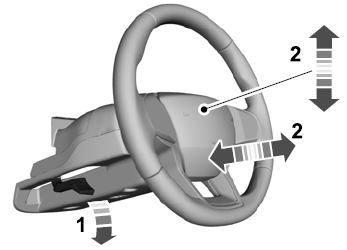
    Lincoln Aviator. Column

    Lock the steering column.

    read more

     
    Copyright © 2025 www.liaviator2.com