
Lincoln Aviator: Customer Assistance / Fuses
 Reporting Safety Defects (Canada Only)
If you believe that your vehicle has a defect
which could cause a crash or could cause
injury or death, you should immediately
inform Transport Canada and Ford of
Canada...

Other information:
Lincoln Aviator 2020-2026 Service Manual: Removal and Installation - Rear Lower Arm
Special Tool(s) / General Equipment 204-592Separator, Lower Arm Ball JointTKIT-2006C-FFMFLMTKIT-2006C-LMTKIT-2006C-ROW Vehicle/Axle Stands Removal NOTICE: Suspension fasteners are critical parts that affect the performance of vital components and systems...
Lincoln Aviator 2020-2026 Owners Manual: Recommended Towing Weights
Note: Do not exceed the trailer weight for your vehicle configuration listed in the chart below. Note: Be sure to take into consideration trailer frontal area. Do not exceed 55 ft² (5.11 m²) if your vehicle can tow a class III trailer. Note: Your vehicle could have reduced performance when operating at high altitudes and when heavily loaded or towing a trailer...
Categories
- Manuals Home
- Lincoln Aviator Owners Manual
- Lincoln Aviator Service Manual
- Description and Operation - Body and Frame
- Fuel Quality
- General Procedures - Transmission Fluid Drain and Refill
- New on site
- Most important about car
Remote Control
Passive Key
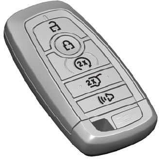
The passive key operates the power locks and the remote start system. The passive key must be in your vehicle to use the push button start.
Note: You may not be able to shift out of park (P) unless the passive key is inside your vehicle.

Copyright © 2026 www.liaviator2.com