Lincoln Aviator: Glass, Frames and Mechanisms / General Procedures - Lead Terminal Repair
Materials
| Name | Specification |
|---|---|
| Motorcraft® Ultra-Clear Spray Glass Cleaner ZC-23 |
ESR-M14P5-A |
Repair
-
Bring the vehicle up to at least the specified room temperature or above.
-
NOTE: The new terminal covers the original terminal location, but it must be placed so the terminal conductive areas will be placed on a good conductive base.
- Terminal Kit — Back Glass 4F1Z-14421-AA
Material: Motorcraft® Ultra-Clear Spray Glass Cleaner / ZC-23 (ESR-M14P5-A)
-
NOTICE: Do not use any type of flame torch or flame-heated soldering gun for this procedure. Use of these tools provide inadequate heat generation at the tip and the exhaust heat can cause damage to plastic trim parts in the area. Use only an electric soldering gun with 100 watts or more of power. Before using the soldering gun, be sure to melt a small amount of rosin core solder to the tip. The solder will assist in achieving better heat transfer from the soldering gun tip to the new terminal.
NOTE: Depending on the original terminal location, and whether the terminal is covered by pillar trim, determines where to locate the new terminal. Some grid line bus bars may only allow the placement of the terminal above or below the original tab location due to space limitations. For most vehicle applications, the replacement tab location covers the original tab location, but still allows the replacement tab to attach to the bus bar on good conductive material.
Place the replacement terminal type A over the original tab location, making sure the conductive areas of the terminal will be on a good conductive area. Do not place the terminal tab foot on the original location, which does not have conductive material.
-
Hold the terminal in place with an item such as a
regular lead pencil at a 90 degree angle from the terminal (Holding at
other than a 90 degree angle may allow the terminal to slip when the
solder liquefies).
-
NOTE: The new terminal has pre-applied solder, flux and temperature-sensitive paint. The paint provides a visual indication when the terminal has reached the correct temperature to melt solder on the terminal. When the correct temperature is achieved, the temperature paint liquefies and changes color.
Place the soldering gun tip on the top of the terminal, but not on the painted areas of the tab. Energize the soldering gun and watch for the painted area of the terminal to liquefy and change color. The paint should liquefy in approximately 25-45 seconds after heating. As soon as the paint color completely changes on either side of the terminal, de-energize the soldering gun and continue to hold the terminal in place with the soldering gun and pencil for an additional 30 seconds.
-
Remove the soldering gun and pencil from the terminal.
Allow the terminal to cool for another 2 minutes before attaching the
wiring lead to the terminal.
-
Attach the electrical lead connection to this terminal, turn on the heated rear window and verify the operation.
 General Procedures - Heated Window Grid Wire Repair
Materials
Name
Specification
Motorcraft® Ultra-Clear Spray Glass CleanerZC-23
ESR-M14P5-A
Motorcraft® Rear Window Defroster RepairPM-11
WSB-M4J58-B
Motorcraft® Lacquer Touch-Up PaintPMPC-19500-XXXXA, PMPM-19500-XXXXG, PMPP-19500-XXXXA
ESR-M2P100-C
Inspection
Using a bright lamp in the vehicle, inspect the grid
wire from the exterior...
 General Procedures - Power Door Window Initialization
Initialization
WARNING:
Before beginning any service procedure in this
section, refer to Safety Warnings in section 100-00 General Information...
Other information:
Lincoln Aviator 2020-2026 Service Manual: Removal and Installation - Passenger Side Temperature Door Actuator
Removal Fully lower the glove compartment. Disconnect the check strap. Push the stop tabs inward. Remove the scres and the passenger side tempreature door actuator. Disconnect the electrical connector...
Lincoln Aviator 2020-2026 Owners Manual: System Settings
The system has optional setting menus available. The system stores the last known selection for each of these settings. You do not need to readjust your settings each time you switch the system on. Mode: This setting allows you to select which of the system features you can enable...
Categories
- Manuals Home
- Lincoln Aviator Owners Manual
- Lincoln Aviator Service Manual
- Description and Operation - Jacking and Lifting
- Description and Operation - Body and Frame
- Keyless Entry
- New on site
- Most important about car
Children and Airbags
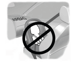
WARNING: Airbags can kill or injure a child in a child restraint. Never place a rear-facing child restraint in front of an active airbag. If you must use a forward-facing child restraint in the front seat, move the seat upon which the child restraint is installed all the way back.