Lincoln Aviator: Lane Keeping System / System Settings
The system has optional setting menus available. The system stores the last known selection for each of these settings. You do not need to readjust your settings each time you switch the system on.
Mode: This setting allows you to select which of the system features you can enable.
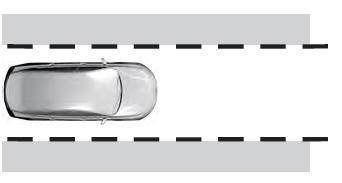
Alert only – Provides a steering wheel vibration when the system detects an unintended lane departure.
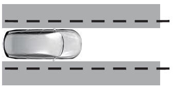
Aid only – Provides steering assistance toward the lane center when the system detects an unintended lane departure.
- Alert.
- Aid.
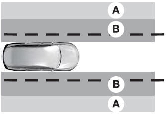
Alert and Aid – Provides steering assistance toward the lane center.
If your vehicle continues drifting out of the lane after the lane keeping aid corrects the vehicle, the system provides a steering wheel vibration.
If your vehicle stays to one side of the lane after the lane keeping aid corrects your vehicle and then subsequently drifts out of the lane again, the system only provides an Alert at the steering wheel.
Note: The Alert and Aid diagrams illustrate general zone coverage. They do not provide exact zone parameters.
Intensity: This setting affects the intensity of the steering wheel vibration used for the Alert and Alert and Aid modes. This setting does not affect the Aid mode.
- Low.
- Normal.
- High.
 Switching the System On and Off
Note: The on or off setting is stored until it
is manually changed, unless a MyKey is
detected. If the system detects a MyKey, it
defaults to on and the mode sets to Alert...
 System Display
When you switch the system on, a graphic
of lane markings appears in the information
display.
When you switch the system off, the lane
marking graphics do not display...
Other information:
Lincoln Aviator 2020-2026 Owners Manual: Manual Park Release
WARNING: When doing this procedure, you need to take the transmission out of park (P) which means your vehicle can roll freely. To avoid unwanted vehicle movement, always fully apply the parking brake prior to doing this procedure. Use wheels chocks if appropriate...
Lincoln Aviator 2020-2026 Service Manual: Removal and Installation - Upper Arm
Special Tool(s) / General Equipment 204-592Separator, Lower Arm Ball JointTKIT-2006C-FFMFLMTKIT-2006C-LMTKIT-2006C-ROW Vehicle/Axle Stands Removal NOTICE: Suspension fasteners are critical parts that affect the performance of vital components and systems...
Categories
- Manuals Home
- Lincoln Aviator Owners Manual
- Lincoln Aviator Service Manual
- Wireless Accessory Charger (If Equipped)
- Resetting the System
- Changing the Front Wiper Blades - Vehicles With: Heated Wiper Blades
- New on site
- Most important about car
Children and Airbags
WARNING: Airbags can kill or injure a child in a child restraint. Never place a rear-facing child restraint in front of an active airbag. If you must use a forward-facing child restraint in the front seat, move the seat upon which the child restraint is installed all the way back.
