Lincoln Aviator: Lane Keeping System / System Display

Lincoln Aviator. System Display

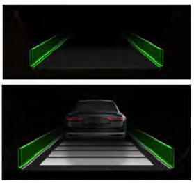
When you switch the system on, a graphic of lane markings appears in the information display.

When you switch the system off, the lane marking graphics do not display.

While the system is on, the color of the lane markings change to indicate the system status. These colors represent the following:

Gray: Indicates that the system is temporarily unable to provide a warning or intervention on the indicated side. This may be because:

  • Your vehicle is under the activation speed.
  • The direction indicator is active.
  • Your vehicle is in a dynamic maneuver.
  • The road has no or poor lane markings in the camera field-of-view.

The camera is obscured or unable to detect the lane markings due to environmental, traffic or vehicle conditions. For example, significant sun angles, shadows, snow, heavy rain or fog, following a large vehicle that is blocking or shadowing the lane or poor headlamp illumination.

See Troubleshooting for additional information.

Green: Indicates that the system is available or ready to provide a warning or intervention on the indicated side.

Animated graphic: Indicates that the system is providing or has just provided a lane keeping aid intervention.

Red: Indicates that the system is providing or has just provided a lane keeping alert warning.

The system can be temporarily suppressed at any time by the following:

  • Quick braking.
  • Fast acceleration.
  • Using the direction indicator.
  • Evasive steering maneuver.
  • Driving too close to the lane markings.

    System Settings

    The system has optional setting menus available. The system stores the last known selection for each of these settings. You do not need to readjust your settings each time you switch the system on...

    Troubleshooting

    ..

    Other information:

    Lincoln Aviator 2020-2025 Service Manual: Diagnosis and Testing - Particulate Filter System


    Diagnostic Trouble Code (DTC) Chart Diagnostics in this manual assume a certain skill level and knowledge of Ford-specific diagnostic practices.REFER to: Diagnostic Methods (100-00 General Information, Description and Operation).   Diagnostic Trouble Code Chart Module   DTC Description Action   PCM P226D:00 Particulate Filter Deteriorated/Missing Substrate Bank 1: No Sub Type Information   GO to Pinpoint Test RA   PCM P226E:00 Particulate Filter Deteriorated/Missing Substrate Bank 2: No Sub Type Information   GO to Pinpoint Test RA   PCM P242F:00 Particulate Filter Restriction - Ash Accumulation (Bank 1): No Sub Type Information   GO to Pinpoint Test RA   PCM P243A:00 Particulate Filter Restriction - Ash Accumulation (Bank 2): No Sub Type Information   GO to Pinpoint Test RA   PCM P243B:00 Particulate Filter Restriction - Forced Limited Power (Bank 2): No Sub Type Information   GO to Pinpoint Test RA   PCM P2452:00 Particulate Filter Pressure Sensor A Circuit: No Sub Type Information   GO to Pinpoint Test RC   PCM P2453:00 Particulate Filter Pressure Sensor A Circuit Range/Performance: No Sub Type Information   GO to Pinpoint Test RC   PCM P2454:00 Particulate Filter Pressure Sensor A Circuit Low: No Sub Type Information   GO to Pinpoint Test RC   PCM P2455:00 Particulate Filter Pressure Sensor A Circuit High: No Sub Type Information   GO to Pinpoint Test RC   PCM P2456:00 Particulate Filter Pressure Sensor Circuit A Intermittent/Erratic: No Sub Type Information   GO to Pinpoint Test RC   PCM P245E:00 Particulate Filter Pressure Sensor B Circuit: No Sub Type Information   GO to Pinpoint Test RC   PCM P245F:00 Particulate Filter Pressure Sensor B Circuit Range/Performance: No Sub Type Information   GO to Pinpoint Test RC   PCM P2460:00 Particulate Filter Pressure Sensor B Circuit Low: No Sub Type Information   GO to Pinpoint Test RC   PCM P2461:00 Particulate Filter Pressure Sensor B Circuit High: No Sub Type Information   GO to Pinpoint Test RC   PCM P2462:00 Particulate Filter Pressure Sensor Circuit B Intermittent/Erratic: No Sub Type Information   GO to Pinpoint Test RC   PCM P246C:00 Particulate Filter Restriction - Forced Limited Power (Bank 1): No Sub Type Information   GO to Pinpoint Test RA   PCM P2CE5:00 Particulate Filter Pressure Sensor C Circuit: No Sub Type Information   GO to Pinpoint Test RC   PCM P2CE6:00 Particulate Filter Pressure Sensor C Circuit Range/Performance: No Sub Type Information   GO to Pinpoint Test RC   PCM P2CE7:00 Particulate Filter Pressure Sensor C Circuit Low: No Sub Type Information   GO to Pinpoint Test RC   PCM P2CE8:00 Particulate Filter Pressure Sensor C Circuit High: No Sub Type Information   GO to Pinpoint Test RC   PCM P2CE9:00 Particulate Filter Pressure Sensor Circuit C Intermittent/Erratic: No Sub Type Information   GO to Pinpoint Test RC   PCM P2CEA:00 Particulate Filter Pressure Sensor D Circuit: No Sub Type Information   GO to Pinpoint Test RC   PCM P2CEB:00 Particulate Filter Pressure Sensor D Circuit Range/Performance: No Sub Type Information   GO to Pinpoint Test RC   PCM P2CEC:00 Particulate Filter Pressure Sensor D Circuit Low: No Sub Type Information   GO to Pinpoint Test RC   PCM P2CED:00 Particulate Filter Pressure Sensor D Circuit High: No Sub Type Information   GO to Pinpoint Test RC   PCM P2CEE:00 Particulate Filter Pressure Sensor Circuit D Intermittent/Erratic: No Sub Type Information   GO to Pinpoint Test RC   PCM U0601:00 Lost Communication With Particulate Filter Pressure Sensor A: No Sub Type Information   GO to Pinpoint Test RC   PCM U0602:00 Lost Communication With Particulate Filter Pressure Sensor B: No Sub Type Information   GO to Pinpoint Test RC   PCM U0696:00 Lost Communication With Particulate Filter Pressure Sensor C: No Sub Type Information   GO to Pinpoint Test RC   PCM U0697:00 Lost Communication With Particulate Filter Pressure Sensor D: No Sub Type Information   GO to Pinpoint Test RC Global Customer Symptom Code (GCSC) Chart Diagnostics in this manual assume a certain skill level and knowledge of Ford-specific diagnostic practices...

    Lincoln Aviator 2020-2025 Service Manual: Description and Operation - Front Suspension - Overview


    Overview The RWD front suspension consists of the following components: Front and rear lower arms Rear lower arm ball joints Stabilizer bar, bushings and links Ride height sensors (Vehicles with Continuously Controlled Damping (CCD) Suspension) Passive or dynamically controlled shock absorber and spring assembly (Continuously Controlled Damping (CCD)) Upper control arms Wheel bearings and wheel hubs Wheel knuckles Wheel studs The front suspension uses a double ball joint short long arm suspension system...

    Categories

    Locking and Unlocking the Doors from Inside

    Lincoln Aviator. Locking and Unlocking the Doors from Inside

    Unlock. Lock.

    Locking the Doors

    Press the lock switch on the door interior trim panel. The doors can no longer be released using the exterior door handle switches and the luggage compartment locks.

    read more

     
    Copyright © 2025 www.liaviator2.com