Lincoln Aviator: Module Configuration / General Procedures - Module Programming

Check

NOTE: Perform the following pre-checks to make sure module programming completes without errors.

  1. Start the programming session in KOEO.
  1. Make sure the vehicle battery is fully charged or is connected to a battery charger. The battery state of charge should be 12.6 - 13.6 volts during vehicle programming.
  1. NOTE: A good internet connection is necessary.

    Inspect the VCM II or VCMM and cables for damage. Make sure cables remain connected throughout the programming procedure.
  1. Turn off all unnecessary accessories, such as radio, A/C, climate controlled seats, headlamps, interior and demand lamps.
  1. Disconnect any aftermarket accessories, such as remote start, security alarm and power inverter.
  1. For Plug-in hybrid and electric vehicles, disconnect the external charge cord from the charge port.
  1. Disable Microsoft Windows sleep mode, screensaver and hibernation modes.

Programming

NOTE: If the diagnostic software does not load or if the vehicle cannot be identified properly, make sure there is a good internet connection and the VCM II or VCMM is properly connected to the DLC.

  1. Log into FDRS.
  1. NOTE: Vehicle information is automatically retrieved by the diagnostic software and a Network Test is run. Vehicle identification data appears on the screen when this is complete.

    Click 'Read VIN from Vehicle' or manually enter the VIN.
  1. NOTE: Available modules are shown on the LH side of the screen, and available procedures are listed on the RH side of the screen. Modules that are communicating are highlighted in green.

    Select Toolbox tab.
  1. NOTE: If a module is integrated within another module, both modules will automatically program during this process. For example, if the ACM is selected, the DACMC (if integrated with the ACM) is also programmed.

    From the list on the LH side of the screen, select the module that requires a programming procedure to be completed.
  1. From the list on the RH side of the screen, select PMI or Module Configuration.
  1. Click RUN. Follow all on-screen instructions carefully.

Recovery

NOTE: Perform the following steps when programming has resulted in a blank module.

  1. Disconnect the VCM II or VCMM from the DLC and PC.
  1. Launch FDRS and log in.
  1. In the Device Manager window that populates, select CANCEL.
  1. Select the appropriate VIN from the Vehicle Identification menu or use Manual VIN Entry and select GO.
  1. In the Vehicle Communication Device Not Detected window that populates, select CONTINUE. If a Device Explorer window populates, select CANCEL.
  1. After the session has started, reconnect the VCM II/ VCMM to the DLC and the PC. The VCM II/ VCMM icon should turn green in the bottom right corner of the screen. If it does not, troubleshoot the FDRS to VCM II or VCMM connection.
  1. In the Toolbox menu, navigate to the failed module and Download/Run PMI. Follow the on-screen prompts. When asked if the original module is installed, select NO and continue through the installation application.
  1. Once programming has completed, a screen may list additional steps required to complete the programming process. Make sure all applicable steps are followed in order.

    Description and Operation - Module Configuration - System Operation and Component Description

    System Operation Programmable Module Installation (PMI) PMI is a diagnostic scan tool process which configures settings in a new module. Data used for the PMI process is automatically downloaded from the original module and stored when a diagnostic scan tool session is started...

    Electronic Feature Group

    ..

    Other information:

    Lincoln Aviator 2020-2023 Service Manual: Diagnosis and Testing - Parking Aid


    Diagnostic Trouble Code (DTC) Chart Diagnostics in this manual assume a certain skill level and knowledge of Ford-specific diagnostic practices. REFER to: Diagnostic Methods (100-00 General Information, Description and Operation).   Diagnostic Trouble Code Chart Module   DTC Description Action   APIM C1001:01 Vision System Camera:General Electrical Failure   GO to Pinpoint Test A   APIM C1001:01 Vision System Camera:General Electrical Failure   GO to Pinpoint Test J   APIM C1001:02 Vision System Camera:General Signal Failure   GO to Pinpoint Test A   APIM C1001:1C Vision System Camera:Circuit Voltage Out Of Range   GO to Pinpoint Test A   APIM C1001:4B Vision System Camera:Over Temperature   GO to Pinpoint Test H   APIM C1001:55 Vision System Camera:Not Configured   GO to Pinpoint Test I   APIM C1001:81 Vision System Camera:Invalid Serial Data Received   GO to Pinpoint Test A   APIM C1001:87 Vision System Camera:Missing Message   GO to Pinpoint Test A   IPMB B115E:31 Camera Module:No Signal   GO to Pinpoint Test L   IPMB B115E:49 Camera Module:Internal Electronic Failure   GO to Pinpoint Test T   IPMB B12BE:31 Left Front Camera:No Signal   GO to Pinpoint Test N   IPMB B12BE:49 Left Front Camera:Internal Electronic Failure   GO to Pinpoint Test U   IPMB B12BF:31 Right Front Camera:No Signal   GO to Pinpoint Test O   IPMB B12BF:49 Right Front Camera:Internal Electronic Failure   GO to Pinpoint Test V   IPMB B148E:31 Front Camera:No Signal   GO to Pinpoint Test M   IPMB B148E:49 Front Camera:Internal Electronic Failure   GO to Pinpoint Test W   IPMB B14A5:11 Multi-Camera View Switch:Circuit Short To Ground   GO to Pinpoint Test P   IPMB C1001:78 Vision System Camera:Alignment Or Adjustment Incorrect   GO to Pinpoint Test X   IPMB U0100:00 Lost Communication With ECM/PCM "A":No Sub Type Information   GO to Pinpoint Test Y   IPMB U0121:00 Lost Communication With Anti-Lock Brake System (ABS) Control Module:No Sub Type Information   GO to Pinpoint Test Z   IPMB U0121:87 Lost Communication With Anti-Lock Brake System (ABS) Control Module "A":Missing Message   GO to Pinpoint Test Z   IPMB U0131:00 Lost Communication With Power Steering Control Module:No Sub-Type Information   GO to Pinpoint Test AA   IPMB U0131:87 Lost Communication With Power Steering Control Module "A":Missing Message   GO to Pinpoint Test AA   IPMB U0138:00 Lost Communication with All Terrain Control Module:No Sub Type Information   GO to Pinpoint Test AB   IPMB U0140:00 Lost Communication With Body Control Module:No Sub Type Information   GO to Pinpoint Test AC   IPMB U0146:00 Lost Communication With Gateway "A":No Sub Type Information   GO to Pinpoint Test AD   IPMB U0212:00 Lost Communication With Steering Column Control Module:No Sub Type Information   GO to Pinpoint Test AJ   IPMB U0253:87 Lost Communication With Accessory Protocol Interface Module:Missing Message   GO to Pinpoint Test AK   IPMB U0293:00 Lost Communication with Hybrid/EV Powertrain Control Module:No Sub Type Information   GO to Pinpoint Test Y   IPMB U0300:57 Internal Control Module Software Incompatibility:Invalid/Incompatible Software Component   GO to Pinpoint Test AN   IPMB U0401:00 Invalid Data Received from ECM/PCM A:No Sub Type Information   GO to Pinpoint Test Y   IPMB U0415:00 Invalid Data Received from Anti-Lock Brake System (ABS) Control Module "A":No Sub Type Information   GO to Pinpoint Test Z   IPMB U0420:00 Invalid Data Received from Power Steering Control Module "A":No Sub Type Information   GO to Pinpoint Test AA   IPMB U0422:00 Invalid Data Received From Body Control Module:No Sub Type Information   GO to Pinpoint Test AC   IPMB U0423:82 Invalid Data Received from Instrument Panel Cluster Control Module:Alive/Sequence Counter Incorrect/Not Updated   GO to Pinpoint Test AE   IPMB U0424:00 Invalid Data Received From HVAC Control Module:No Sub Type Information   GO to Pinpoint Test AF   IPMB U0424:82 Invalid Data Received From HVAC Control Module:Alive/Sequence Counter Incorrect/Not Updated   GO to Pinpoint Test AF   IPMB U0428:00 Invalid Data Received From Steering Angle Sensor Module:No Sub Type Information   GO to Pinpoint Test AG   IPMB U0485:82 Invalid Data Received From Radio:Alive/Sequence Counter Incorrect/Not Updated   GO to Pinpoint Test AH   IPMB U0553:82 Invalid Data Received From Lighting Control Module-Rear "B":Alive/Sequence Counter Incorrect/Not Updated   GO to Pinpoint Test AI   IPMB U0554:00 Invalid Data Received From Accessory Protocol Interface Module:No Sub Type Information   GO to Pinpoint Test AK   IPMB U0554:82 Invalid Data Received From Accessory Protocol Interface Module:Alive/Sequence Counter Incorrect/Not Updated   GO to Pinpoint Test AK   IPMB U0594:00 Invalid Data Received From Hybrid/EV Powertrain Control Module:No Sub Type Information   GO to Pinpoint Test Y   IPMB U1000:11 Solid State Driver Protection Active -Driver Disabled:Circuit Short To Ground   GO to Pinpoint Test AL   IPMB U2024:41 Control Module Cal-Config Data:General Checksum Failure   GO to Pinpoint Test AM   IPMB U2100:00 Initial Configuration Not Complete:No Sub Type Information   GO to Pinpoint Test AM   IPMB U2101:00 Control Module Configuration Incompatible:No Sub Type Information   GO to Pinpoint Test AM   IPMB U3000:42 Control Module:General Memory Failure   GO to Pinpoint Test AN   IPMB U3000:49 Control Module:Internal Electronic Failure   GO to Pinpoint Test AN Symptom Chart(s) Rear Only Parking Aid Camera Diagnostics in this manual assume a certain skill level and knowledge of Ford-specific diagnostic practices...

    Lincoln Aviator 2020-2023 Service Manual: General Procedures - Headlamp Adjustment


    Adjustment NOTE: If the flash video link does not load or is incompatible with your browser, a .wmv version of the video can be accessed at: http://www.fordservicecontent.com/Ford_Content/videos/FusionHeadlampAdj2.wmv Click on the link above to view video...

    Categories

    Remote Control

    Passive Key

    Lincoln Aviator. Remote Control

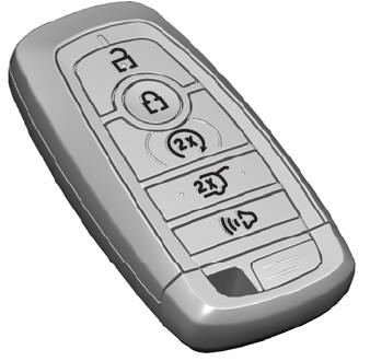
    The passive key operates the power locks and the remote start system. The passive key must be in your vehicle to use the push button start.

    Note: You may not be able to shift out of park (P) unless the passive key is inside your vehicle.

    read more

     
    Copyright © 2023 www.liaviator2.com