
Lincoln Aviator: Exterior Trim and Ornamentation / Removal and Installation - A-Pillar Moulding

Special Tool(s) / General Equipment

Interior Trim Remover

Removal

NOTICE: Only use moderate force.

NOTE: Removal steps in this procedure may contain installation details.

NOTE: LH side shown, RH similar.

    • Using a non-marring trim removal tool disengage the retainer clips starting approximately 9 inches from the top.
      Use the General Equipment: Interior Trim Remover
    • Slide the trim tool downwards and pry outward to disengage the clips.
  1. Remove the bolts.
    Torque: 13 lb.in (1.5 Nm)
  1. NOTE: The component should be reused unless damaged.

    NOTE: Remove any clips that stay attached to the bracket when removed.

    Release the clips and remove the A-pillar Moulding.

Installation

  1. To install, reverse the removal procedure.

    General Procedures - Finish Panel Repair

    Repair NOTE: Mouldings located on the front and rear window frames may experience minor scratches from vehicle shipment or car wash racks. The imperfections may be repaired instead of replacing components by following the steps below...

    Removal and Installation - Front Door Moulding

    Removal NOTE: Removal steps in this procedure may contain installation details. NOTE: LH door shown, RH door similar. NOTE: Do not use excessive force when removing retainers, to avoid damage to moulding...

    Other information:

    Lincoln Aviator 2020-2026 Service Manual: Removal and Installation - Brake Pedal and Bracket


    Removal NOTE: Removal steps in this procedure may contain installation details. Remove the BCM. Refer to: Body Control Module (BCM) (419-10 Multifunction Electronic Modules, Removal and Installation). NOTICE: Do not service the brake pedal or brake booster without first removing the stoplamp switch...

    Lincoln Aviator 2020-2026 Service Manual: Diagnosis and Testing - Body Control Module (BCM)


    Diagnostic Trouble Code (DTC) Chart Diagnostics in this manual assume a certain skill level and knowledge of Ford-specific diagnostic practices. REFER to: Diagnostic Methods (100-00 General Information, Description and Operation).   Diagnostic Trouble Code Chart Module   DTC Description Action   BCM B11D9:16 Vehicle Battery:Circuit Voltage Below Threshold   GO to Pinpoint Test Y   BCM B11D9:17 Vehicle Battery:Circuit Voltage Above Threshold   GO to Pinpoint Test Z   BCM U0100:87 Lost Communication With ECM/PCM "A":Missing Message   GO to Pinpoint Test A   BCM U0121:87 Lost Communication With Anti-Lock Brake System (ABS) Control Module:Missing Message   GO to Pinpoint Test B   BCM U0131:87 Lost Communication With Power Steering Control Module:Missing Message   GO to Pinpoint Test C   BCM U0151:87 Lost Communication With Restraints Control Module:Missing Message   GO to Pinpoint Test D   BCM U0155:87 Lost Communication With Instrument Panel Cluster (IPC) Control Module:Missing Message   GO to Pinpoint Test E   BCM U0166:87 Lost Communication With Auxiliary Heater Control Module:Missing Message   GO to Pinpoint Test F   BCM U0184:87 Lost Communication With Radio:Missing Message   GO to Pinpoint Test G   BCM U0198:87 Lost Communication With Telematic Control Module: Missing Message   GO to Pinpoint Test H   BCM U0199:87 Lost Communication With "Door Control Module A":Missing Message   GO to Pinpoint Test I   BCM U019B:87 Lost Communication With Battery Charger Control Module:Missing Message   GO to Pinpoint Test J   BCM U0200:87 Lost Communication With "Door Control Module B":Missing Message   GO to Pinpoint Test K   BCM U0208:87 Lost Communication With "Seat Control Module A":Missing Message   GO to Pinpoint Test L   BCM U0212:87 Lost Communication With Steering Column Control Module:Missing Message   GO to Pinpoint Test M   BCM U0230:87 Lost Communication With Rear Gate Module:Missing Message   GO to Pinpoint Test N   BCM U0232:87 Lost Communication With Side Obstacle Detection Control Module "A":Missing Message   GO to Pinpoint Test O   BCM U0233:87 Lost Communication With Side Obstacle Detection Control Module "B":Missing Message   GO to Pinpoint Test P   BCM U023A:87 Lost Communication With Image Processing Control Module A:Missing Message   GO to Pinpoint Test Q   BCM U0252:87 Lost Communication With Lighting Control Module-Rear "B":Missing Message   GO to Pinpoint Test R   BCM U0253:87 Lost Communication With Accessory Protocol Interface Module:Missing Message   GO to Pinpoint Test S   BCM U0256:87 Lost Communication With Front Controls Interface Module "A":Missing Message   GO to Pinpoint Test T   BCM U0293:87 Lost Communication With Hybrid/EV Powertrain Control Module "A":Missing Message   GO to Pinpoint Test U   BCM U1000:00 Solid State Driver Protection Active:Driver Disabled: No Sub Type Information   GO to Pinpoint Test V   BCM U2005:85 Vehicle Speed:Signal Above Allowable Range   GO to Pinpoint Test W   BCM U2100:00 Initial Configuration Not Complete:No Sub Type Information   GO to Pinpoint Test X   BCM U2101:00 Control Module Configuration Inomplete:No Sub Type Information   GO to Pinpoint Test X   BCM U2200:00 Control Module Configuration Memory Corrupt:No Sub Type Information   GO to Pinpoint Test X   BCM U3000:49 Control Module:Internal Electronic Failure   GO to Pinpoint Test AA   BCM U3006:16 Control Module Input Power “A”:Circuit Voltage Below Threshold   GO to Pinpoint Test Y   BCM U3006:17 Control Module Input Power “A”:Circuit Voltage Above Threshold   GO to Pinpoint Test Z   BCM U3006:1C Control Module Input Power “A”:Circuit Voltage Out of Range   GO to Pinpoint Test Y   BCM U3006:1C Control Module Input Power “A”:Circuit Voltage Out of Range   GO to Pinpoint Test Z   BCM U3007:16 Control Module Input Power "B":Circuit Voltage Below Threshold   GO to Pinpoint Test Y   BCM U3007:17 Control Module Input Power "B":Circuit Voltage Above Threshold   GO to Pinpoint Test Z   BCM U3013:16 Control Module Input Power "C":Circuit Voltage Below Threshold   GO to Pinpoint Test Y   BCM U3013:17 Control Module Input Power "C":Circuit Voltage Above Threshold   GO to Pinpoint Test Z   BCM U3014:16 Control Module Input Power "D":Circuit Voltage Below Threshold   GO to Pinpoint Test Y   BCM U3014:17 Control Module Input Power "D":Circuit Voltage Above Threshold   GO to Pinpoint Test Z Symptom Chart Symptom Chart: Multifunction Electronic Modules Diagnostics in this manual assume a certain skill level and knowledge of Ford-specific diagnostic practices...

    Categories

    Adjusting the Steering Wheel - Vehicles With: Manual Adjustable Steering Column

    WARNING: Do not adjust the steering wheel when your vehicle is moving.

    Note: Make sure that you are sitting in the correct position.

    Unlock the steering column. Adjust the steering wheel to the desired position.
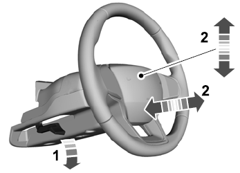
    Lincoln Aviator. Column

    Lock the steering column.

    read more

     
    Copyright © 2026 www.liaviator2.com