Lincoln Aviator: Four-Wheel Drive Systems / Removal and Installation - All-Wheel Drive (AWD) Module
Special Tool(s) / General Equipment
| Interior Trim Remover |
Removal
NOTE: Removal steps in this procedure may contain installation details.
NOTE: If installing a new all-wheel drive module, it is necessary to upload the module configuration information to the scan tool prior to removing the module. This information must be downloaded into the new all-wheel drive module after installation. Using a diagnostic scan tool, begin the PMI process for the all-wheel drive module following the onscreen instructions
-
LH side
Refer to: Front Seat (501-10A Front Seats, Removal and Installation).
-
LH side
Refer to: Front Scuff Plate Trim Panel (501-05 Interior Trim and Ornamentation, Removal and Installation).
-
NOTE: Seats removed for clarity.
Release the tabs and remove the lower B-pillar trim panel cover.
.jpg) |
-
NOTE:
Remove the lower B-pillar trim panel.
-
Release the lower B-pillar trim panel clips.
Use the General Equipment: Interior Trim Remover
-
Feed the front seatbelt retractor and pretensioner through the opening in the lower B-pillar trim panel.
-
Release the lower B-pillar trim panel clips.
.jpg) |
-
-
Release the clip
-
Detach the floor from the main floor and position aside.
-
Release the clip
.jpg) |
-
-
Release the clips
-
Detach the floor from the main floor and position aside.
-
Release the clips
.jpg) |
-
Remove the module.
-
Release the tab from the connector.
-
Disconnect the electrical connector from the module.
-
Release the tab from the connector.
.jpg) |
-
Remove the bolts and the AWD module.
Torque: 55 lb.in (6.2 Nm)
.jpg) |
Installation
-
To install, reverse the removal procedure.
-
NOTE: Carry out the remaining steps only if installing a new all - wheel drive module.
Using the scan tool, complete the PMI process for the AWD module following the on-screen instructions.
-
NOTE: The transfer case X-Digit alpha numeric bar code is located on the label attached to the transfer case.
Using the scan tool, complete the Active Torque Coupling Configuration for the AWD module.
 Removal and Installation - All Terrain Control Module (ATCM)
Special Tool(s) /
General Equipment
Interior Trim Remover
Removal
NOTE:
Removal steps in this procedure may contain installation details...
 Removal and Installation - Transfer Case Clutch Actuator
Materials
Name
Specification
Motorcraft® MERCON® LV Automatic Transmission FluidXT-10-QLVC
WSS-M2C938-AMERCON® LV,
Removal
NOTE:
Removal steps in this procedure may contain installation details...
Other information:
Lincoln Aviator 2020-2026 Service Manual: Description and Operation - Fuel System - Overview
Overview NOTICE: Repairs of the fuel system are to be achieved only by replacement of the failed component(s). Repair of a fuel system component should not be attempted. NOTICE: If directed during assembly of fuel system components, lubricate any seal(s) only with specified material...
Lincoln Aviator 2020-2026 Service Manual: Removal and Installation - Front Seat Power Lumbar Assembly - Vehicles Without: Multi-Contour Seats
Removal NOTE: Driver seat shown, passenger seat similar. Remove the front seat. Refer to: Front Seat (501-10A Front Seats, Removal and Installation). Remove the front seat backrest panel. Refer to: Front Seat Backrest Panel (501-10A Front Seats, Removal and Installation)...
Categories
- Manuals Home
- Lincoln Aviator Owners Manual
- Lincoln Aviator Service Manual
- Body and Paint
- USB Port and Power Point Locations
- Configuring The Head Up Display
- New on site
- Most important about car
Adjusting the Steering Wheel - Vehicles With: Manual Adjustable Steering Column
WARNING: Do not adjust the steering wheel when your vehicle is moving.
Note: Make sure that you are sitting in the correct position.
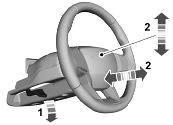
Unlock the steering column. Adjust the steering wheel to the desired position.
