Lincoln Aviator 2020-2026 Service Manual / Powertrain / Automatic Transmission / Four-Wheel Drive Systems / Removal and Installation - All Terrain Control Module (ATCM)
Lincoln Aviator: Four-Wheel Drive Systems / Removal and Installation - All Terrain Control Module (ATCM)
Special Tool(s) / General Equipment
| Interior Trim Remover |
Removal
NOTE: Removal steps in this procedure may contain installation details.
- Selectable Drive Mode Switch (Console rotary type)
-
Release the retainers and remove the LH floor console side trim panel.
Use the General Equipment: Interior Trim Remover
.jpg) |
-
Release the retainers and remove the RH floor console side trim panel.
Use the General Equipment: Interior Trim Remover
.jpg) |
-
Open the center console arm rest panel.
.jpg) |
-
Remove the FCIMB.
Refer to: Front Controls Interface Module B (FCIMB) (415-00 Information and Entertainment System - General Information, Removal and Installation).
-
Remove both top console side panel bolts.
Torque: 22 lb.in (2.5 Nm)
.jpg) |
-
Remove both top console side trim panels.
-
Remove the bolts.
Use the General Equipment: Interior Trim Remover
Torque: 22 lb.in (2.5 Nm)
-
Release the retainers and remove the RH and LH floor console side trim panels.
-
Remove the bolts.
.jpg) |
-
Remove both floor console bolts.
-
Remove the bolts.
Torque: 28 lb.in (3.2 Nm)
-
Remove the screws.
Torque: 17 lb.in (1.9 Nm)
-
Remove the bolts.
.jpg) |
-
Release the clips, detach the console top panel,
disconnect the electrical connectors and remove the console top panel.
.jpg) |
-
Remove the module.
-
Remove the screws.
-
Remove the switch.
Torque: 17 lb.in (1.9 Nm)
-
Remove the screws.
.jpg) |
Installation
-
To install, reverse the removal procedure.
 General Procedures - Transfer Case Clutch Learn
Activation
Update the AWD (all-wheel drive) module to the
latest calibration available. Module reprogramming will erase stored
transfer case clutch kiss point values and initiate rapid kiss point
learn procedure...
 Removal and Installation - All-Wheel Drive (AWD) Module
Special Tool(s) /
General Equipment
Interior Trim Remover
Removal
NOTE:
Removal steps in this procedure may contain installation details...
Other information:
Lincoln Aviator 2020-2026 Service Manual: Removal and Installation - Gateway Module A (GWM)
Removal NOTE: Removal steps in this procedure may contain installation details. NOTE: If installing a new module, it is necessary to upload the module configuration information to the scan tool prior to removing the module. This information must be downloaded into the new module after installation...
Lincoln Aviator 2020-2026 Service Manual: Removal and Installation - Second Row Air Flow Shut Off Door Actuator
Removal Remove the floor console. Refer to: Floor Console (501-12 Instrument Panel and Console, Removal and Installation). Remove the screws and the second row air flow shut off door actuator. Disconnect the electrical connector...
Categories
- Manuals Home
- Lincoln Aviator Owners Manual
- Lincoln Aviator Service Manual
- Disabling Auto-Start-Stop
- Interior Lamps
- Remove and Reinstall the Battery
- New on site
- Most important about car
Activating Intelligent Access
The intelligent access key must be within 3 ft (1 m) of the door or luggage compartment you intend to lock or unlock.
At a Door
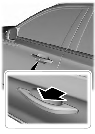
Electronic door handles are on each door. Gently depress the switch inside the exterior door handle to unlock and open the door. An unlock symbol illuminates on the door window trim indicating your vehicle is unlocked.

Copyright © 2026 www.liaviator2.com
