Lincoln Aviator 2020-2026 Service Manual / Electrical / Information and Entertainment Systems / Information and Entertainment System - General Information / Removal and Installation - Audio Front Control Module (ACM)
Lincoln Aviator: Information and Entertainment System - General Information / Removal and Installation - Audio Front Control Module (ACM)
Removal
NOTE: Removal steps in this procedure may contain installation details.
-
NOTE: If installing a new module, it is necessary to upload the module configuration information to the scan tool prior to removing the module. This information must be downloaded into the new module after installation.
Using a diagnostic scan tool, begin the PMI process for the ACM following the onscreen instructions.
-
Remove the RH loadspace trim panel.
Refer to: Loadspace Trim Panel (501-05 Interior Trim and Ornamentation, Removal and Installation).
-
Separate the wiring harness retainers.
.jpg) |
-
Disconnect the electrical connectors and position the wiring aside.
.jpg) |
-
Remove the nuts, stud-nut and the ACM.
Torque: 106 lb.in (12 Nm)
.jpg) |
Installation
-
To install, reverse the removal procedure.
-
NOTE: This step is only necessary when installing a new component.
Using a diagnostic scan tool, complete the PMI process for the ACM following the on-screen instructions.
 Removal and Installation - Audio Digital Signal Processing (DSP) Module
Removal
NOTE:
Removal steps in this procedure may contain installation details.
NOTE:
If installing a new DSP,
it is necessary to upload the module configuration information to the
scan tool prior to removing the module...
 Removal and Installation - Audio Unit Antenna Cable
Removal
NOTE:
Removal steps in this procedure may contain installation details.
NOTE:
The original equipment antenna cables arepart of the wiring
harnesses and cannot be removed...
Other information:
Lincoln Aviator 2020-2026 Service Manual: Removal and Installation - Rear Door Lock Control Switch
Special Tool(s) / General Equipment Interior Trim Remover Removal NOTE: LH (left-hand) side shown, RH (right-hand) side similar. Remove the rear door window control switch bezel assembly. Release the locking tabs from the rear door window control switch bezel assembly...
Lincoln Aviator 2020-2026 Service Manual: General Procedures - Heated Window Grid Wire Repair
Materials Name Specification Motorcraft® Ultra-Clear Spray Glass CleanerZC-23 ESR-M14P5-A Motorcraft® Rear Window Defroster RepairPM-11 WSB-M4J58-B Motorcraft® Lacquer Touch-Up PaintPMPC-19500-XXXXA, PMPM-19500-XXXXG, PMPP-19500-XXXXA ESR-M2P100-C Inspection Using a bright lamp in the vehicle, inspect the grid wire from the exterior...
Categories
- Manuals Home
- Lincoln Aviator Owners Manual
- Lincoln Aviator Service Manual
- Child Safety Locks
- Interior Lamps
- Description and Operation - Body and Frame
- New on site
- Most important about car
Remote Control
Passive Key

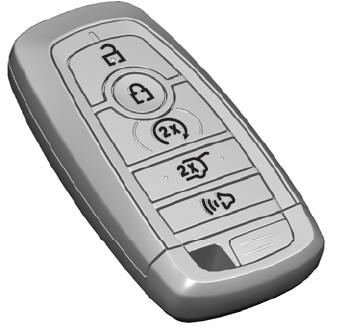
The passive key operates the power locks and the remote start system. The passive key must be in your vehicle to use the push button start.
Note: You may not be able to shift out of park (P) unless the passive key is inside your vehicle.
Copyright © 2026 www.liaviator2.com
