Lincoln Aviator: Interior Trim and Ornamentation / Removal and Installation - B-Pillar Trim Panel

Special Tool(s) / General Equipment

Interior Trim Remover

Removal

NOTE: LH (left hand) shown, RH (right hand) similar.

Upper and lower B-pillar trim panels

  1. Remove the following items:
    1. Remove the front scuff plate trim panel.
      Refer to: Front Scuff Plate Trim Panel (501-05 Interior Trim and Ornamentation, Removal and Installation).
    1. Remove the rear scuff plate trim panel.
      Refer to: Rear Scuff Plate Trim Panel (501-05 Interior Trim and Ornamentation, Removal and Installation).
  1. Position the front seat in the full forward position.
  1. NOTE: Seats removed for clarity.

    Release the tabs and remove the lower B-pillar trim panel cover.
    Use the General Equipment: Interior Trim Remover
  1. NOTE: Seats removed for clarity.

    Release the clips and remove the lower B-pillar trim panel. .
    Use the General Equipment: Interior Trim Remover

Upper B-pillar trim panel

  WARNING: The following procedure prescribes critical repair steps required for correct restraint system operation during a crash. Follow all notes and steps carefully. Failure to follow step instructions may result in incorrect operation of the restraint system and increases the risk of serious personal injury or death in a crash.

NOTE: Removal steps in this procedure may contain installation details.

  1.   WARNING: Before beginning any service procedure in this manual, refer to health and safety warnings in section 100-00 General Information. Failure to follow this instruction may result in serious personal injury.

    Refer to: Pyrotechnic Device Health and Safety Precautions (100-00 General Information, Description and Operation).
  1. Depower the SRS.
    Refer to: Supplemental Restraint System (SRS) Depowering (501-20B Supplemental Restraint System, General Procedures).
  1. NOTE: Seats removed for clarity.

    Disconnect the front seatbelt retractor and pretensioner electrical connector.
  1. NOTE: Seats removed for clarity.

    Remove the front seatbelt retractor and pretenioner anchor nut.
    Torque: 35 lb.ft (47 Nm)
  1. Remove the upper B-pillar trim panel bolt.
    Torque: 80 lb.in (9 Nm)

  1. Remove the upper B-pillar trim panel.
    1. Release the upper B-pillar trim panel lower clip.
      Use the General Equipment: Interior Trim Remover
    1. Pull downward and outward on the upper B-pillar trim panel releasing the upper tabs.
    1. Feed the front seatbelt retractor and pretenioner through the opening in the upper B-pillar trim panel.

Installation

NOTE: During installation, make sure the seatbelt webbing is not twisted and the seatbelts and buckles are acccessible to the occupants.

  1. To install, reverse the removal procedure.
  1. Inspect and position the front door and rear door weather strip lips so that they overlap the top of the B-pillar trim panels.
  1. Repower the SRS.
    Refer to: Supplemental Restraint System (SRS) Repowering (501-20B Supplemental Restraint System, General Procedures).
  1. Check the seatbelt system for correct operation.
    Refer to: Seatbelt Systems (501-20A Seatbelt Systems, Diagnosis and Testing).

    Removal and Installation - A-Pillar Trim Panel

    Special Tool(s) / General Equipment Interior Trim Remover Removal NOTE: LH (left hand) shown, RH (right hand) similar. Release the clips and remove the instrument panel side trim panel...

    Removal and Installation - C-Pillar Trim Panel

    Special Tool(s) / General Equipment Interior Trim Remover Removal NOTE: LH (left hand) shown, RH (right hand) similar. NOTE: Removal steps in this procedure may contain installation details...

    Other information:

    Lincoln Aviator 2020-2025 Owners Manual: Tire Change Procedure


    WARNING: The jack supplied with this vehicle is only intended for changing wheels. Do not use the vehicle jack other than when you are changing a wheel in an emergency. WARNING: Check that the vehicle jack is not damaged or deformed and the thread is lubricated and clean...

    Lincoln Aviator 2020-2025 Service Manual: Diagnosis and Testing - Parking Aid


    Diagnostic Trouble Code (DTC) Chart Diagnostics in this manual assume a certain skill level and knowledge of Ford-specific diagnostic practices. REFER to: Diagnostic Methods (100-00 General Information, Description and Operation).   Diagnostic Trouble Code Chart Module   DTC Description Action   IPMB B1303:13 Park Assist Switch:Circuit Open   GO to Pinpoint Test D   IPMB B1303:9E Park Assist Switch:Stuck On   GO to Pinpoint Test D   IPMB B1B36:08 Right Front Outer Sensor:Bus Signal/Message Failure   GO to Pinpoint Test I   IPMB B1B36:96 Right Front Outer Sensor: Component Internal Failure   GO to Pinpoint Test N   IPMB B1B36:98 Right Front Outer Sensor:Component Or System Over Temperature   GO to Pinpoint Test O   IPMB B1B38:08 Right Front Inner Sensor:Bus Signal/Message Failure   GO to Pinpoint Test J   IPMB B1B38:96 Right Front Inner Sensor: Component Internal Failure   GO to Pinpoint Test N   IPMB B1B38:98 Right Front Inner Sensor:Component Or System Over Temperature   GO to Pinpoint Test O   IPMB B1B40:08 Left Front Outer Sensor:Bus Signal/Message Failure   GO to Pinpoint Test K   IPMB B1B40:96 Left Front Outer Sensor: Component Internal Failure   GO to Pinpoint Test N   IPMB B1B40:98 Left Front Outer Sensor:Component Or System Over Temperature   GO to Pinpoint Test O   IPMB B1B42:08 Left Front Inner Sensor:Bus Signal/Message Failure   GO to Pinpoint Test L   IPMB B1B42:96 Left Front Inner Sensor: Component Internal Failure   GO to Pinpoint Test N   IPMB B1B42:98 Left Front Inner Sensor:Component Or System Over Temperature   GO to Pinpoint Test O   IPMB B1B44:08 Right Rear Outer Sensor:Bus Signal/Message Failure   GO to Pinpoint Test E   IPMB B1B44:96 Right Rear Outer Sensor: Component Internal Failure   GO to Pinpoint Test M   IPMB B1B44:98 Right Rear Outer Sensor:Component Or System Over Temperature   GO to Pinpoint Test P   IPMB B1B46:08 Right Rear Inner Sensor:Bus Signal/Message Failure   GO to Pinpoint Test F   IPMB B1B46:96 Right Rear Inner Sensor: Component Internal Failure   GO to Pinpoint Test M   IPMB B1B46:98 Right Rear Inner Sensor:Component Or System Over Temperature   GO to Pinpoint Test P   IPMB B1B48:08 Left Rear Outer Sensor:Bus Signal/Message Failure   GO to Pinpoint Test G   IPMB B1B48:96 Left Rear Outer Sensor: Component Internal Failure   GO to Pinpoint Test M   IPMB B1B48:98 Left Rear Outer Sensor:Component Or System Over Temperature   GO to Pinpoint Test P   IPMB B1B50:08 Left Rear Inner Sensor:Bus Signal/Message Failure   GO to Pinpoint Test H   IPMB B1B50:96 Left Rear Inner Sensor: Component Internal Failure   GO to Pinpoint Test M   IPMB B1B50:98 Left Rear Inner Sensor:Component Or System Over Temperature   GO to Pinpoint Test P   IPMB B1B57:11 Front Sensors Power Circuit: Circuit Short To Ground   GO to Pinpoint Test B   IPMB B1B58:11 Rear Sensors Power Circuit: Circuit Short To Ground   GO to Pinpoint Test C   IPMB U0428:00 Invalid Data Received From Steering Angle Sensor Module:No Sub Type Information   GO to Pinpoint Test Z   PAM B1303:13 Park Assist Switch:Circuit Open   GO to Pinpoint Test D   PAM B1303:9E Park Assist Switch:Stuck On   GO to Pinpoint Test D   PAM B1B36:08 Right Front Outer Sensor:Bus Signal/Message Failure   GO to Pinpoint Test I   PAM B1B36:1F Right Front Outer Sensor:Circuit Intermittent   GO to Pinpoint Test I   PAM B1B36:31 Right Front Outer Sensor:No Signal   GO to Pinpoint Test I   PAM B1B36:96 Right Front Outer Sensor: Component Internal Failure   GO to Pinpoint Test N   PAM B1B36:98 Right Front Outer Sensor:Component Or System Over Temperature   GO to Pinpoint Test O   PAM B1B38:08 Right Front Inner Sensor:Bus Signal/Message Failure   GO to Pinpoint Test J   PAM B1B38:1F Right Front Inner Sensor:Circuit Intermittent   GO to Pinpoint Test J   PAM B1B38:31 Right Front Inner Sensor:No Signal   GO to Pinpoint Test J   PAM B1B38:96 Right Front Inner Sensor: Component Internal Failure   GO to Pinpoint Test N   PAM B1B38:98 Right Front Inner Sensor:Component Or System Over Temperature   GO to Pinpoint Test O   PAM B1B40:08 Left Front Outer Sensor:Bus Signal/Message Failure   GO to Pinpoint Test K   PAM B1B40:1F Left Front Outer Sensor:Circuit Intermittent   GO to Pinpoint Test K   PAM B1B40:31 Left Front Outer Sensor:No Signal   GO to Pinpoint Test K   PAM B1B40:96 Left Front Outer Sensor: Component Internal Failure   GO to Pinpoint Test N   PAM B1B40:98 Left Front Outer Sensor:Component Or System Over Temperature   GO to Pinpoint Test O   PAM B1B42:08 Left Front Inner Sensor:Bus Signal/Message Failure   GO to Pinpoint Test L   PAM B1B42:1F Left Front Inner Sensor:Circuit Intermittent   GO to Pinpoint Test L   PAM B1B42:31 Left Front Inner Sensor:No Signal   GO to Pinpoint Test L   PAM B1B42:96 Left Front Inner Sensor: Component Internal Failure   GO to Pinpoint Test N   PAM B1B42:98 Left Front Inner Sensor:Component Or System Over Temperature   GO to Pinpoint Test O   PAM B1B44:08 Right Rear Outer Sensor:Bus Signal/Message Failure   GO to Pinpoint Test E   PAM B1B44:1F Right Rear Outer Sensor:Circuit Intermittent   GO to Pinpoint Test E   PAM B1B44:31 Right Rear Outer Sensor:No Signal   GO to Pinpoint Test E   PAM B1B44:96 Right Rear Outer Sensor: Component Internal Failure   GO to Pinpoint Test M   PAM B1B44:98 Right Rear Outer Sensor:Component Or System Over Temperature   GO to Pinpoint Test P   PAM B1B46:08 Right Rear Inner Sensor:Bus Signal/Message Failure   GO to Pinpoint Test F   PAM B1B46:1F Right Rear Inner Sensor:Circuit Intermittent   GO to Pinpoint Test F   PAM B1B46:31 Right Rear Inner Sensor:No Signal   GO to Pinpoint Test F   PAM B1B46:96 Right Rear Inner Sensor: Component Internal Failure   GO to Pinpoint Test M   PAM B1B46:98 Right Rear Inner Sensor:Component Or System Over Temperature   GO to Pinpoint Test P   PAM B1B48:08 Left Rear Outer Sensor:Bus Signal/Message Failure   GO to Pinpoint Test G   PAM B1B48:1F Left Rear Outer Sensor:Circuit Intermittent   GO to Pinpoint Test G   PAM B1B48:31 Left Rear Outer Sensor:No Signal   GO to Pinpoint Test G   PAM B1B48:96 Left Rear Outer Sensor: Component Internal Failure   GO to Pinpoint Test M   PAM B1B48:98 Left Rear Outer Sensor:Component Or System Over Temperature   GO to Pinpoint Test P   PAM B1B50:08 Left Rear Inner Sensor:Bus Signal/Message Failure   GO to Pinpoint Test H   PAM B1B50:1F Left Rear Inner Sensor:Circuit Intermittent   GO to Pinpoint Test H   PAM B1B50:31 Left Rear Inner Sensor:No Signal   GO to Pinpoint Test H   PAM B1B50:96 Left Rear Inner Sensor: Component Internal Failure   GO to Pinpoint Test M   PAM B1B50:98 Left Rear Inner Sensor:Component Or System Over Temperature   GO to Pinpoint Test P   PAM B1B57:11 Front Sensors Power Circuit: Circuit Short To Ground   GO to Pinpoint Test B   PAM B1B58:11 Rear Sensors Power Circuit: Circuit Short To Ground   GO to Pinpoint Test C   PAM U0100:00 Lost Communication With ECM/PCM "A": No Sub Type Information   GO to Pinpoint Test R   PAM U0121:00 Lost Communication With Anti-Lock Brake System (ABS) Control Module: No Sub Type Information   GO to Pinpoint Test S   PAM U0131:00 Lost Communication With Power Steering Control Module: No Sub-Type Information   GO to Pinpoint Test T   PAM U0138:00 Lost Communication with All Terrain Control Module:No Sub Type Information   GO to Pinpoint Test U   PAM U0140:00 Lost Communication With Body Control Module: No Sub Type Information   GO to Pinpoint Test V   PAM U0146:00 Lost Communication With Gateway "A": No Sub Type Information   GO to Pinpoint Test W   PAM U0155:00 Lost Communication With Instrument Panel Cluster (IPC) Control Module: No Sub Type Information   GO to Pinpoint Test X   PAM U0164:00 Lost Communication With HVAC Control Module: No Sub Type Information   GO to Pinpoint Test Y   PAM U0212:00 Lost Communication With Steering Column Control Module: No Sub Type Information   GO to Pinpoint Test AB   PAM U0252:00 Lost Communication With Lighting Control Module- Rear "B": No Sub Type Information   GO to Pinpoint Test AC   PAM U0293:00 Lost Communication with Hybrid/EV Powertrain Control Module:No Sub Type Information   GO to Pinpoint Test R   PAM U0300:57 Internal Control Module Software Incompatibility:Invalid/Incompatible Software Component   GO to Pinpoint Test AG   PAM U0401:00 Invalid Data Received from ECM/PCM A:No Sub Type Information   GO to Pinpoint Test R   PAM U0415:00 Invalid Data Received from Anti-Lock Brake System (ABS) Control Module "A":No Sub Type Information   GO to Pinpoint Test S   PAM U0420:00 Invalid Data Received from Power Steering Control Module "A":No Sub Type Information   GO to Pinpoint Test T   PAM U0422:00 Invalid Data Received From Body Control Module:No Sub Type Information   GO to Pinpoint Test V   PAM U0423:82 Invalid Data Received from Instrument Panel Cluster Control Module:Alive/Sequence Counter Incorrect/Not Updated   GO to Pinpoint Test X   PAM U0424:00 Invalid Data Received From HVAC Control Module:No Sub Type Information   GO to Pinpoint Test Y   PAM U0424:82 Invalid Data Received From HVAC Control Module:Alive/Sequence Counter Incorrect/Not Updated   GO to Pinpoint Test Y   PAM U0485:82 Invalid Data Received From Radio:Alive/Sequence Counter Incorrect/Not Updated   GO to Pinpoint Test AA   PAM U0553:82 Invalid Data Received From Lighting Control Module-Rear "B":Alive/Sequence Counter Incorrect/Not Updated   GO to Pinpoint Test AC   PAM U0554:00 Invalid Data Received From Accessory Protocol Interface Module:No Sub Type Information   GO to Pinpoint Test AD   PAM U0554:82 Invalid Data Received From Accessory Protocol Interface Module:Alive/Sequence Counter Incorrect/Not Updated   GO to Pinpoint Test AD   PAM U0594:00 Invalid Data Received From Hybrid/EV Powertrain Control Module:No Sub Type Information   GO to Pinpoint Test R   PAM U1000:00 Solid State Driver Protection Active -Driver Disabled:No Sub Type Information   GO to Pinpoint Test AE   PAM U2024:41 Control Module Cal-Config Data:General Checksum Failure   GO to Pinpoint Test AF   PAM U2100:00 Initial Configuration Not Complete:No Sub Type Information   GO to Pinpoint Test AF   PAM U2101:00 Control Module Configuration Incompatible:No Sub Type Information   GO to Pinpoint Test AF   PAM U3000:44 Control Module:Data Memory Failure   GO to Pinpoint Test AG   PAM U3000:45 Control Module:Program Memory Failure   GO to Pinpoint Test AG   PAM U3000:46 Control Module:Calibration/Parameter Memory Failure   GO to Pinpoint Test AG   PAM U3000:49 Control Module:Internal Electronic Failure   GO to Pinpoint Test AG Symptom Chart(s)   Symptom Chart: Parking Aid Condition Possible Sources Actions A module does not communicate with the diagnostic scan tool Fuse Wiring, terminals or connectors PAM IPMB   REFER to: Communications Network (418-00 Module Communications Network, Diagnosis and Testing)...

    Categories

    Remote Control

    Passive Key

    Lincoln Aviator. Remote Control

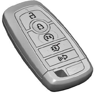
    The passive key operates the power locks and the remote start system. The passive key must be in your vehicle to use the push button start.

    Note: You may not be able to shift out of park (P) unless the passive key is inside your vehicle.

    read more

     
    Copyright © 2025 www.liaviator2.com