
Lincoln Aviator 2020-2026 Service Manual / Electrical / Battery and Charging System / Battery, Mounting and Cables / Removal and Installation - Battery
Lincoln Aviator: Battery, Mounting and Cables / Removal and Installation - Battery
Removal
NOTE: Removal steps in this procedure may contain installation details.
-
Disconnect the battery/batteries.
Refer to: Battery Disconnect and Connect (414-01 Battery, Mounting and Cables, General Procedures).
Vehicles with H7 AGM battery
-
-
Disconnect the vent hose from the battery.
-
Fully loosen and remove the battery hold-down bolt and clamp. Remove the battery.
Torque: 62 lb.in (7 Nm)
-
Disconnect the vent hose from the battery.
.jpg) |
Vehicles with H8 AGM battery
-
-
Disconnect the vent hose from the battery.
-
Fully loosen and remove the battery hold-down bolt and clamp. Remove the battery.
Torque: 62 lb.in (7 Nm)
-
Disconnect the vent hose from the battery.
.jpg) |
Installation
-
To install, reverse the removal procedure.
-
If installing a new battery, use the scan tool to carry
out the Battery Monitoring System (BMS) reset after the battery is
connected.
 Removal and Installation - Auxiliary Battery Cable
Removal
NOTE:
This procedure provides information about routing, retaining
points and connectors of the cable. It does not include the steps for
removing components to gain access to the cable...
 Removal and Installation - Battery Cables - 3.0L EcoBoost
Removal
NOTE:
This procedure provides information about routing, retaining
points and connectors of the cable. It does not include the steps for
removing components to gain access to the cable...
Other information:
Lincoln Aviator 2020-2026 Owners Manual: Using Active Park Assist
The parking button is above the transmission selector, just below the display screen. Press the parking button then touch the Active Park Assist icon on the display screen to bring up full screen notifications. Touch the soft keys on the display screen to switch between Parallel Park In, Perpendicular Park In or Parallel Park Out parking modes...
Lincoln Aviator 2020-2026 Service Manual: Diagnosis and Testing - Collision Warning and Collision Avoidance System
DTC Charts Diagnostics in this manual assume a certain skill level and knowledge of Ford-specific diagnostic practices. REFER to: Diagnostic Methods (100-00 General Information, Description and Operation). DTC Chart: HUD Module NOTE: The HUD module Diagnostic Trouble Codes (DTCs) are diagnosed in the Instrument, Message Center and Warning Chime section of the workshop manual...
Categories
- Manuals Home
- Lincoln Aviator Owners Manual
- Lincoln Aviator Service Manual
- Opening and Closing the Hood
- Resetting the System
- Child Safety Locks
- New on site
- Most important about car
Child Safety Locks
When the child safety locks are set, you cannot open the rear doors from the inside.
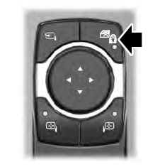
The child safety lock control is on the driver door.
Press the control to switch the child safety locks on. Press the control again to switch them off. A light on the child safety control illuminates when you switch them on.

Copyright © 2026 www.liaviator2.com