
Lincoln Aviator 2020-2026 Service Manual / Electrical / Battery and Charging System / Battery, Mounting and Cables
Lincoln Aviator: Battery and Charging System / Battery, Mounting and Cables
- Specifications
- Description and Operation - Battery and Cables - Overview
- Description and Operation - Battery and Cables - System Operation and Component Description
- Diagnosis and Testing - Battery
- General Procedures - Battery Charging
- General Procedures - Battery Disconnect and Connect
- General Procedures - Battery Drain Check
- Removal and Installation - Auxiliary Battery
- Removal and Installation - Auxiliary Battery Cable
- Removal and Installation - Battery
- Removal and Installation - Battery Cables - 3.0L EcoBoost
- Removal and Installation - Battery Current Sensor
- Removal and Installation - Battery Monitoring Sensor
- Removal and Installation - Battery Tray
- Removal and Installation - Generator Current Sensor
 Diagnosis and Testing - Charging System
Diagnostic Trouble Code (DTC) Chart
Diagnostics in this manual assume a certain skill level and knowledge of Ford-specific diagnostic practices. REFER to: Diagnostic Methods (100-00 General Information, Description and Operation)...
 Specifications
Battery Specifications
Base and Reserve without trailer tow vehicles
Item
Specification
Voltage
12 Volts
Cold Cranking Amps (CCA) measured at -18 C (-0...
Other information:
Lincoln Aviator 2020-2026 Service Manual: General Procedures - Air Suspension System Depressurize and Pressurize
Pressure release Assemble the following items: Shut off valve Pressure regulator with gauge R-134a low side refrigerant line fitting Air line male quick connect fitting Position the vehicle on a hoist...
Lincoln Aviator 2020-2026 Service Manual: General Procedures - RTV Sealing Surface Cleaning and Preparation
Special Tool(s) / General Equipment Plastic Scraper Nylon Bristle Disk Plastic Razor Blade Lint-Free Towel Isopropyl Alcohol – 90 Percent Minimum Materials Name Specification Motorcraft® Silicone Gasket RemoverZC-30-A - Motorcraft® Metal Surface Prep WipesZC-31-B - Motorcraft® Engine Shampoo and DegreaserZC-20 ESR-M14P3-A Motorcraft® Metal Brake Parts CleanerPM-4-A, PM-4-B - Cleaning NOTICE: This procedure is only to be used on the sealing surfaces of metal components...
Categories
- Manuals Home
- Lincoln Aviator Owners Manual
- Lincoln Aviator Service Manual
- USB Port and Power Point Locations
- Body and Paint
- Opening and Closing the Hood
- New on site
- Most important about car
Child Safety Locks
When the child safety locks are set, you cannot open the rear doors from the inside.
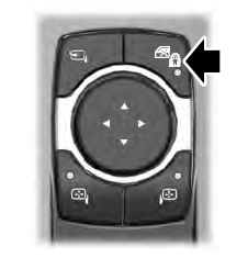
The child safety lock control is on the driver door.
Press the control to switch the child safety locks on. Press the control again to switch them off. A light on the child safety control illuminates when you switch them on.

Copyright © 2026 www.liaviator2.com