Lincoln Aviator: Front Disc Brake / Removal and Installation - Brake Caliper
Removal
.jpg) WARNING:
Service actions on vehicles equipped with electronic brake
booster and electronic parking brakes may cause unexpected brake
application, which could result in injury to hands or fingers. Put the
brake system into service mode prior to servicing or removing any brake
components. Failure to follow this instruction may result in serious
personal injury.
WARNING:
Service actions on vehicles equipped with electronic brake
booster and electronic parking brakes may cause unexpected brake
application, which could result in injury to hands or fingers. Put the
brake system into service mode prior to servicing or removing any brake
components. Failure to follow this instruction may result in serious
personal injury.
NOTICE: Make sure that all openings are sealed.
NOTICE: If the fluid is spilled on the paintwork, the affected area must be immediately washed down with cold water.
NOTE: Removal steps in this procedure may contain installation details.
-
Activate the brake service mode.
Refer to: Brake Service Mode Activation and Deactivation (206-00 Brake System - General Information, General Procedures).
-
Remove the wheel and tire.
Refer to: Wheel and Tire (204-04A Wheels and Tires, Removal and Installation).
-
NOTE: Make sure all openings are sealed.
Remove the bolt and disconnect the brake hose. Discard the washers.
Torque: 26 lb.ft (35 Nm)
.jpg) |
-
Remove the bolts and the brake caliper.
Torque:
M8 :: 20 lb.ft (27 Nm)
M10 :: 34 lb.ft (46 Nm)
.jpg) |
Installation
NOTICE: Make sure that the brake hose is not twisted when installing the brake caliper or damage to the brake flexible hose may occur.
-
To install, reverse the removal procedure.
-
Deactivate the brake service mode.
Refer to: Brake Service Mode Activation and Deactivation (206-00 Brake System - General Information, General Procedures).
-
Bleed the brake system.
Refer to: Brake System Pressure Bleeding (206-00 Brake System - General Information, General Procedures).
 Removal and Installation - Brake Caliper Anchor Plate
Removal
NOTE:
Removal steps in this procedure may contain installation details.
Remove the brake pads.
Refer to: Brake Pads (206-03 Front Disc Brake, Removal and Installation)...
Other information:
Lincoln Aviator 2020-2026 Service Manual: Removal and Installation - Roof Rear Frame
Special Tool(s) / General Equipment Resistance Spotwelding Equipment Spot Weld Drill Bit Locking Pliers Removal WARNING: Before beginning any service procedure in this manual, refer to health and safety warnings in section 100-00 General Information...
Lincoln Aviator 2020-2026 Owners Manual: Tire and Wheel Alignment
A bad jolt from hitting a curb or pothole can cause the front end of your vehicle to become misaligned or cause damage to your tires. If your vehicle seems to pull to one side when you are driving, the wheels may be out of alignment. Have an authorized dealer check the wheel alignment periodically...
Categories
- Manuals Home
- Lincoln Aviator Owners Manual
- Lincoln Aviator Service Manual
- Locking and Unlocking
- Anti-Theft Alarm
- Interior Lamps
- New on site
- Most important about car
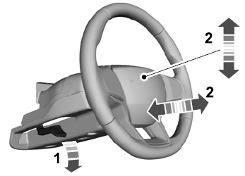
Adjusting the Steering Wheel - Vehicles With: Manual Adjustable Steering Column
WARNING: Do not adjust the steering wheel when your vehicle is moving.
Note: Make sure that you are sitting in the correct position.
Unlock the steering column. Adjust the steering wheel to the desired position.

