Lincoln Aviator: Supplemental Restraint System / Removal and Installation - C-Pillar Side Impact Sensor
Removal
.jpg) WARNING:
The following procedure prescribes critical repair steps
required for correct restraint system operation during a crash. Follow
all notes and steps carefully. Failure to follow step instructions may
result in incorrect operation of the restraint system and increases the
risk of serious personal injury or death in a crash.
WARNING:
The following procedure prescribes critical repair steps
required for correct restraint system operation during a crash. Follow
all notes and steps carefully. Failure to follow step instructions may
result in incorrect operation of the restraint system and increases the
risk of serious personal injury or death in a crash.
NOTE: LH (left-hand) shown, RH (right-hand) similar.
NOTE: Removal steps in this procedure may contain installation details.
-
Refer to: Pyrotechnic Device Health and Safety Precautions (100-00 General Information, Description and Operation)..jpg) WARNING:
Before beginning any service procedure in this
manual, refer to health and safety warnings in section 100-00 General
Information. Failure to follow this instruction may result in serious
personal injury.
WARNING:
Before beginning any service procedure in this
manual, refer to health and safety warnings in section 100-00 General
Information. Failure to follow this instruction may result in serious
personal injury.
-
Depower the SRS.
Refer to: Supplemental Restraint System (SRS) Depowering (501-20B Supplemental Restraint System, General Procedures).
-
Position the rear door weather-strip aside.
.jpg) |
-
Release the clips and remove the rear door scuff plate trim panel.
.jpg) |
-
Fold the second row outboard seat to the easy entry position.
.jpg) |
-
Remove the tie down hook.
-
Position the tie down hook bolt cover up
-
Remove the tie down hook bolt.
-
Position the tie down hook bolt cover up
.jpg) |
-
NOTE: The seat is removed for clarity.
Release the clips and position the loadspace trim panel away enough to access the C-pillar side impact sensor.
.jpg) |
-
Remove the C-pillar side impact sensor.
-
Disconnect the electrical connector.
-
Remove the bolt.
Torque: 106 lb.in (12 Nm)
-
Remove the C-pillar side impact sensor.
-
Disconnect the electrical connector.
.jpg) |
Installation
-
NOTE: The C-pillar side impact sensor mating surfaces must be smooth and allow for a flush attachment to each other.
To install, reverse the removal procedure.
-
Repower the SRS.
Refer to: Supplemental Restraint System (SRS) Repowering (501-20B Supplemental Restraint System, General Procedures).
 Removal and Installation - Clockspring
Removal
WARNING:
The following procedure prescribes critical repair steps
required for correct restraint system operation during a crash. Follow
all notes and steps carefully...
 Removal and Installation - Driver Airbag
Removal
WARNING:
The following procedure prescribes critical repair steps
required for correct restraint system operation during a crash. Follow
all notes and steps carefully...
Other information:
Lincoln Aviator 2020-2026 Service Manual: Removal and Installation - Brake Fluid Reservoir
Removal NOTICE: Siphon the brake fluid from the HCU/EBB reservoir, if the reservoir is not emptied there will be a large amount of brake fluid spilled in the engine compartment. NOTE: Removal steps in this procedure may contain installation details...
Lincoln Aviator 2020-2026 Service Manual: General Procedures - Spring Lock Couplings
Special Tool(s) / General Equipment 310-250Disconnect Tool, Fuel LineTKIT-2012A-FLTKIT-2012A-ROW Disconnect NOTICE: When reusing liquid or vapor tube connectors, make sure to use compressed air to remove any foreign material from the connector retaining clip area before separating from the tube or damage to the tube or connector retaining clip can occur...
Categories
- Manuals Home
- Lincoln Aviator Owners Manual
- Lincoln Aviator Service Manual
- Resetting the System
- Body and Paint
- Description and Operation - Body and Frame
- New on site
- Most important about car
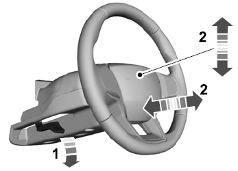
Adjusting the Steering Wheel - Vehicles With: Manual Adjustable Steering Column
WARNING: Do not adjust the steering wheel when your vehicle is moving.
Note: Make sure that you are sitting in the correct position.
Unlock the steering column. Adjust the steering wheel to the desired position.
