Lincoln Aviator: Supplemental Restraint System / Removal and Installation - Clockspring
Removal
.jpg) WARNING:
The following procedure prescribes critical repair steps
required for correct restraint system operation during a crash. Follow
all notes and steps carefully. Failure to follow step instructions may
result in incorrect operation of the restraint system and increases the
risk of serious personal injury or death in a crash.
WARNING:
The following procedure prescribes critical repair steps
required for correct restraint system operation during a crash. Follow
all notes and steps carefully. Failure to follow step instructions may
result in incorrect operation of the restraint system and increases the
risk of serious personal injury or death in a crash.
NOTE: Removal steps in this procedure may contain installation details .
-
Refer to: Pyrotechnic Device Health and Safety Precautions (100-00 General Information, Description and Operation)..jpg) WARNING:
Before beginning any service procedure in this
manual, refer to health and safety warnings in section 100-00 General
Information. Failure to follow this instruction may result in serious
personal injury.
WARNING:
Before beginning any service procedure in this
manual, refer to health and safety warnings in section 100-00 General
Information. Failure to follow this instruction may result in serious
personal injury.
-
Remove the following items:
-
NOTE: Follow the unique instructions or graphic for this step in installation.
Remove the steering wheel.
Refer to: Steering Wheel (211-04 Steering Column, Removal and Installation).
-
Remove the steering column shrouds.
Refer to: Steering Column Shrouds (501-05 Interior Trim and Ornamentation, Removal and Installation).
-
-
-
Disconnect the clockspring electrical connector.
-
Remove the clockspring screws.
-
NOTE: Follow the unique instructions or graphic for this step in installation.
Remove the clockspring.
-
Disconnect the clockspring electrical connector.
.jpg) |
Installation
NOTICE: If installing a new clockspring, do not remove the clockspring anti-rotation key until the steering wheel is installed. If the anti-rotation key has been removed before installing the steering wheel, the clockspring must be centered. Failure to follow this instruction may result in component damage and/or system failure.
-
NOTE: Illustration shows the cancel tab in the off position.
Before installing the clockspring, position the turn signal stalk to the off position.
-
Ensure the turn signal cancel tab is in the off position.
-
Ensure the turn signal cancel tab is in the off position.
.jpg) |
-
To install, reverse the removal procedure.
-
NOTE: This step is only necessary if adjustment or centralizing is required.
Adjust the clockspring.
Refer to: Clockspring Adjustment (501-20 Supplemental Restraint System) .
-
NOTE: Remove the anti-rotation key from a new clockspring after installing the steering wheel.
Install the steering wheel.
Refer to: Steering Wheel (211-04 Steering Column, Removal and Installation).
.jpg) |
 Removal and Installation - C-Pillar Side Impact Sensor
Removal
WARNING:
The following procedure prescribes critical repair steps
required for correct restraint system operation during a crash. Follow
all notes and steps carefully...
Other information:
Lincoln Aviator 2020-2026 Owners Manual: Remote Control
You can use the remote control at any time. When you press the lock button on the remote control, all exterior door handle switches do not release the doors. When you press the unlock button, all exterior door handle switches release the doors. Unlocking the Doors Press the button...
Lincoln Aviator 2020-2026 Service Manual: Description and Operation - Sealer, Underbody Protection Material and Adhesives
Adhesives The correct adhesive bonding is essential to repairing the vehicle correctly. Adhesives and mechanical fasteners are used in certain areas of the body structure in place of welding. In addition to providing a structural bond between components, adhesives can also help prevent wind noise, water leaks, exhaust fumes and dust from entering the vehicle...
Categories
- Manuals Home
- Lincoln Aviator Owners Manual
- Lincoln Aviator Service Manual
- Tire Change Procedure
- Child Safety Locks
- Disabling Auto-Start-Stop
- New on site
- Most important about car
Activating Intelligent Access
The intelligent access key must be within 3 ft (1 m) of the door or luggage compartment you intend to lock or unlock.
At a Door
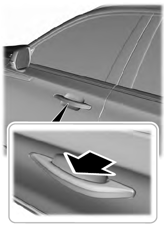
Electronic door handles are on each door. Gently depress the switch inside the exterior door handle to unlock and open the door. An unlock symbol illuminates on the door window trim indicating your vehicle is unlocked.


