Lincoln Aviator 2020-2026 Service Manual / Electrical / Climate Control System / Climate Control System - General Information / Removal and Installation - Climate Control Housing
Lincoln Aviator: Climate Control System - General Information / Removal and Installation - Climate Control Housing
Removal
NOTE: Removal steps in this procedure may contain installation details.
-
Remove the instrument panel.
Refer to: Instrument Panel (501-12 Instrument Panel and Console, Removal and Installation).
-
Remove the bolt, release the clips and remove the lower center instrument panel trim panel.
.jpg) |
-
Remove the bolts and the shift module and mounting plate.
-
Disconnect the electrical connector.
Torque: 44 lb.in (5 Nm)
-
Disconnect the electrical connector.
.jpg) |
-
Remove the bolts, and the nut and washer.
Torque: 62 lb.in (7 Nm)
.jpg) |
-
Remove the bolt, detach the wiring harness retainers and position the wiring harness aside.
Torque: 62 lb.in (7 Nm)
.jpg) |
-
Disconnect the electrical connector(s), detach the
wiring harness retainers and position the wiring harenss aside.
.jpg) |
-
Disconnect the electrical connector(s), detach the
wiring harness retainers and position the wiring harenss aside.
.jpg) |
-
Disconnect the electrical connector.
-
Remove the bolts.
Torque: 13 lb.in (1.5 Nm)
-
Remove the bolt.
Torque: 62 lb.in (7 Nm)
-
Remove the bolts.
.jpg) |
-
Remove screw, detach the harness retainers, and disconnect the electrical connectors.
.jpg) |
-
Remove the bolt, detech the wiring harness retainers and position the wiring harness aside.
Torque: 62 lb.in (7 Nm)
.jpg) |
-
Remove the climate control housing from the in-vehicle cross beam.
.jpg) |
Installation
-
To install, reverse the removal procedure.
 Removal and Installation - Center Registers
Special Tool(s) /
General Equipment
Interior Trim Remover
Removal
NOTE:
Removal steps in this procedure may contain installation details...
 Removal and Installation - Condenser - 3.0L EcoBoost
Removal
NOTICE:
During the removal of components, cap, tape or otherwise
appropriately protect all openings to prevent the ingress of dirt or
other contamination...
Other information:
Lincoln Aviator 2020-2026 Service Manual: General Procedures - Ring Gear Backlash Adjustment
Special Tool(s) / General Equipment 205-220Installer, Differential ShimTKIT-1985-FH Dial Indicator Copper Hammer Adjustment Remove the differential housing cover. Refer to: Differential Housing Cover (205-02 Rear Drive Axle/Differential, Removal and Installation)...
Lincoln Aviator 2020-2026 Service Manual: Removal and Installation - Clockspring
Removal WARNING: The following procedure prescribes critical repair steps required for correct restraint system operation during a crash. Follow all notes and steps carefully. Failure to follow step instructions may result in incorrect operation of the restraint system and increases the risk of serious personal injury or death in a crash...
Categories
- Manuals Home
- Lincoln Aviator Owners Manual
- Lincoln Aviator Service Manual
- Wireless Accessory Charger (If Equipped)
- Keyless Entry
- Description and Operation - Body and Frame
- New on site
- Most important about car
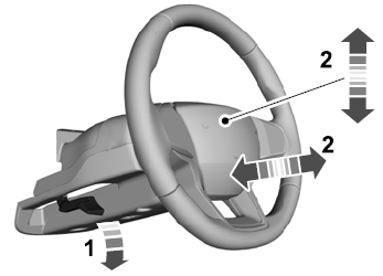
Adjusting the Steering Wheel - Vehicles With: Manual Adjustable Steering Column
WARNING: Do not adjust the steering wheel when your vehicle is moving.
Note: Make sure that you are sitting in the correct position.
Unlock the steering column. Adjust the steering wheel to the desired position.
Copyright © 2026 www.liaviator2.com
