Lincoln Aviator 2020-2026 Service Manual / Body and Paint / Body and Paint / Handles, Locks, Latches and Entry Systems / Removal and Installation - Exterior Front Door Handle
Lincoln Aviator: Handles, Locks, Latches and Entry Systems / Removal and Installation - Exterior Front Door Handle
Removal
NOTE: LH (left-hand) side shown, RH (right-hand) side similar.
NOTE: Removal steps in this procedure may contain installation details.
-
Remove the front door window regulator and motor.
Refer to: Front Door Window Regulator and Motor (501-11 Glass, Frames and Mechanisms, Removal and Installation).
-
Remove the aft front door glass run and bracket.
-
Remove the bolts from the aft front door glass run and bracket.
Torque: 93 lb.in (10.5 Nm)
-
Remove the aft front door glass run and bracket.
-
Remove the bolts from the aft front door glass run and bracket.
.jpg) |
-
Disconnect the electrical connector and position the wiring harness aside.
-
Disconnect the exterior front door handle electrical connector.
-
Release the wiring harness routing clips and position the wiring harness aside.
-
Disconnect the exterior front door handle electrical connector.
.jpg) |
-
Remove the exterior front door handle reinforcement adhesive tape cover.
.jpg) |
-
Remove the exterior front door handle and the exterior front door handle reinforcement.
-
Remove the exterior front door handle reinforcement nuts.
Torque: 80 lb.in (9 Nm)
-
Remove the exterior front door handle reinforcement.
-
Remove the exterior front door handle.
-
Remove the exterior front door handle reinforcement nuts.
.jpg) |
-
Remove the exterior front door handle gaskets.
.jpg) |
Installation
-
To install, reverse the removal procedure.
-
Carry out the power door window initialization.
Refer to: Power Door Window Initialization (501-11 Glass, Frames and Mechanisms, General Procedures).
 Removal and Installation - Door Lock Cylinder
Special Tool(s) /
General Equipment
Interior Trim Remover
Removal
NOTE:
Removal steps in this procedure may contain installation details...
 Removal and Installation - Exterior Front Door Handle Reinforcement
Removal
NOTE:
LH (left-hand) side shown, RH (right-hand) side similar.
NOTE:
Removal steps in this procedure may contain installation details.
Remove the front door window regulator and motor...
Other information:
Lincoln Aviator 2020-2026 Owners Manual: Steering
Electric Power Steering WARNING: The electric power steering system has diagnostic checks that continuously monitor the system. If a fault is detected, a message displays in the information display. Stop your vehicle as soon as it is safe to do so...
Lincoln Aviator 2020-2026 Owners Manual: Autolock (If Equipped)
Autolock locks all the doors when: All doors are closed. The ignition is on. You shift into any gear putting your vehicle in motion. Your vehicle reaches a speed greater than 12 mph (20 km/h). Autolock repeats when: You open then close any door while the ignition is on and your vehicle speed is 9 mph (15 km/h) or lower...
Categories
- Manuals Home
- Lincoln Aviator Owners Manual
- Lincoln Aviator Service Manual
- Anti-Theft Alarm
- Description and Operation - Body and Frame
- Configuring The Head Up Display
- New on site
- Most important about car
Remote Control
Passive Key

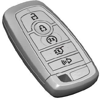
The passive key operates the power locks and the remote start system. The passive key must be in your vehicle to use the push button start.
Note: You may not be able to shift out of park (P) unless the passive key is inside your vehicle.
Copyright © 2026 www.liaviator2.com
