Lincoln Aviator 2020-2026 Service Manual / Powertrain / Engine / Fuel Charging and Controls - 3.0L EcoBoost/3.0L EcoBoost – Hybrid (BQ) / Removal and Installation - High-Pressure Fuel Pump Drive Unit
Lincoln Aviator: Fuel Charging and Controls - 3.0L EcoBoost/3.0L EcoBoost – Hybrid (BQ) / Removal and Installation - High-Pressure Fuel Pump Drive Unit
Removal and Installation
-
The high-pressure fuel pump drive unit is part of the
right cylinder head and is removed in the right camshaft procedure.
Refer to: Cylinder Head RH (303-01A Engine - 3.0L EcoBoost, Removal and Installation).
Refer to: Camshaft RH (303-01A Engine - 3.0L EcoBoost, Removal and Installation).
 Removal and Installation - High-Pressure Fuel Pump
Removal
NOTICE:
Do not loosen any fittings or plugs on the high-pressure fuel pump.
With the vehicle in NEUTRAL, position it on a hoist.
Refer to: Jacking and Lifting (100-02 Jacking and Lifting, Description and Operation)...
 Removal and Installation - Throttle Body
Removal
NOTICE:
The turbocharger compressor vanes can be damaged by even the
smallest particles. When removing any turbocharger or engine air intake
system component, ensure that no debris enters the system...
Other information:
Lincoln Aviator 2020-2026 Owners Manual: Special Operating Conditions Scheduled Maintenance
If you operate your vehicle primarily in any of the following conditions, you need to perform extra maintenance as indicated. If you operate your vehicle occasionally under any of these conditions, it is not necessary to perform the extra maintenance...
Lincoln Aviator 2020-2026 Service Manual: Diagnosis and Testing - Lane Keeping System
DTC Chart(s) Diagnostics in this manual assume a certain skill level and knowledge of Ford-specific diagnostic practices. REFER to: Diagnostic Methods (100-00 General Information, Description and Operation). IPMA DTC Chart DTC Description Action B120C:11 Heater for Windshield Mounted Sensor: Circuit Short To Ground GO to Pinpoint Test C B120C:13 Heater for Windshield Mounted Sensor: Circuit Open GO to Pinpoint Test C B13A6:14 Lane Departure Warning (LDW) Switch Input: Circuit Short To Ground or Open GO to Pinpoint Test A C0072:00 Brake Temperature Too High: No Sub Type Information This DTC sets when the CCM receives a brake over temperature message from the brake system...
Categories
- Manuals Home
- Lincoln Aviator Owners Manual
- Lincoln Aviator Service Manual
- Body and Paint
- Configuring The Head Up Display
- Wireless Accessory Charger (If Equipped)
- New on site
- Most important about car
Activating Intelligent Access
The intelligent access key must be within 3 ft (1 m) of the door or luggage compartment you intend to lock or unlock.
At a Door
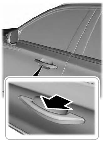
Electronic door handles are on each door. Gently depress the switch inside the exterior door handle to unlock and open the door. An unlock symbol illuminates on the door window trim indicating your vehicle is unlocked.

Copyright © 2026 www.liaviator2.com
