
Lincoln Aviator 2020-2026 Service Manual / Body and Paint / Body and Paint / Handles, Locks, Latches and Entry Systems / Removal and Installation - Liftgate Latch
Lincoln Aviator: Handles, Locks, Latches and Entry Systems / Removal and Installation - Liftgate Latch
Removal
NOTE: Removal steps in this procedure may contain installation details.
-
Remove the liftgate trim panel.
Refer to: Liftgate Trim Panel (501-05 Interior Trim and Ornamentation, Removal and Installation).
-
Remove the liftgate latch bolts.
Torque: 177 lb.in (20 Nm)
.jpg) |
-
NOTE: Liftgate shown transparent for clarity.
Remove the liftgate latch.
-
Disconnect the wiring harness electrical connector(s).
-
Remove the liftgate latch.
-
Disconnect the wiring harness electrical connector(s).
.jpg) |
Installation
-
To install, reverse the removal procedure.
-
Carry out the power liftgate Initialization.
Refer to: Power Liftgate Initialization (501-03 Body Closures, General Procedures).
 Removal and Installation - Keyless Entry Rear Antenna
Special Tool(s) /
General Equipment
Interior Trim Remover
Removal
Remove the luggage compartment floor covering.
NOTE:
LH (left-hand) side shown, RH (right-hand) side similar...
 Removal and Installation - Liftgate Release Switch
Special Tool(s) /
General Equipment
Interior Trim Remover
Removal
Remove the liftgate moulding.
Refer to: Liftgate Moulding (501-08 Exterior Trim and Ornamentation, Removal and Installation)...
Other information:
Lincoln Aviator 2020-2026 Service Manual: Removal and Installation - Front Parking Aid Camera Washer Jet
Removal NOTE: Removal steps in this procedure may contain installation details. Remove the front parking aid camera. Refer to: Front Parking Aid Camera (413-13B Parking Aid - Vehicles With: Parking Aid Camera, Removal and Installation)...
Lincoln Aviator 2020-2026 Service Manual: Specifications
General Specifications Item Specification Base and Reserve without trailer tow vehicles Rating 220 amps Generator amps at 80.6°F (27°C) 98.1 amps at 625 rpm (min) to 180 amps at 2,500 rpm (max) Generator pulley ratio 2...
Categories
- Manuals Home
- Lincoln Aviator Owners Manual
- Lincoln Aviator Service Manual
- Description and Operation - Body and Frame
- Wireless Accessory Charger (If Equipped)
- Drive Modes
- New on site
- Most important about car
Children and Airbags
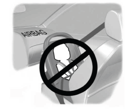
WARNING: Airbags can kill or injure a child in a child restraint. Never place a rear-facing child restraint in front of an active airbag. If you must use a forward-facing child restraint in the front seat, move the seat upon which the child restraint is installed all the way back.

Copyright © 2026 www.liaviator2.com