Lincoln Aviator: Hybrid Vehicle Operation / Starting, Driving and Stopping
Starting
 When you start your vehicle, a
green READY indicator light
appears in the instrument cluster
letting you know that your vehicle is ready
for driving.
The engine may not start because your vehicle has a silent key start feature. This fuel saving feature allows your vehicle to be ready to drive without requiring the gas engine to be running. The indicator remains on when your vehicle is on, whether the engine is running or not, to indicate your vehicle is capable of movement using the electric motor, gas engine or both. Typically, the engine does not start unless the vehicle is cold, a climate control change is requested or you press the accelerator pedal.
Driving
The gas engine automatically starts and stops to provide power when needed and to save fuel when not needed. When coasting at low speeds, coming to a stop, or standing, the gas engine normally shuts down and your vehicle operates in electric-only mode.
Conditions that may cause the engine to start up or remain running include:
- Considerable vehicle acceleration.
- Climbing a hill.
- Charge level of high voltage battery is low.
- High or low outside temperatures in order to provide system heating or cooling.
- Engine not warm enough to provide passenger requested cabin temperature.
- Towing a trailer.
- Selectable drive modes: Certain selectable drive modes may cause the engine to run.
- Live in Drive: Use of the paddle shifters while in drive (D) may cause the engine to run.
Stopping
The gas engine may shut off to conserve fuel as you come to a stop. Restarting your vehicle is not required. Simply step on the accelerator when you are ready to drive.
 Hybrid Vehicle Operation
This hybrid vehicle combines electric and
gasoline propulsion to provide breakthrough
performance and improved efficiency.
Familiarizing yourself with these unique
characteristics provides an optimal driving
experience from your vehicle...
 Transmission Operation. Battery
Transmission Operation
The engine and electric motor together
propel the vehicle through the automatic
transmission. This is normal hybrid operating
and helps deliver fuel efficiency and
performance...
Other information:
Lincoln Aviator 2020-2026 Owners Manual: Automatic Engine Shutdown. Automatic Engine Shutdown Override
Automatic Engine Shutdown For vehicles with a keyless ignition, this feature automatically shuts down the engine if it has been idling for an extended period. The ignition also turns off in order to save battery power. Before your vehicle shuts down, a message appears in the information display showing a timer counting down from 30 seconds...
Lincoln Aviator 2020-2026 Service Manual: Removal and Installation - Rear Door Skin Panel
Special Tool(s) / General Equipment Resistance Spotwelding Equipment Scraper for Straight Edges Grinder Hot Air Gun Knife Spot Weld Drill Bit Locking Pliers Materials Name Specification Metal Bonding AdhesiveTA-1, TA-1-B, 3M™ 08115, LORD Fusor® 108B - Seam SealerTA-2-B, 3M™ 08308, LORD Fusor® 803DTM - Flexible Foam Repair3M™ 08463, LORD Fusor® 121 - Removal WARNING: Electric vehicles damaged by a crash may have compromised high voltage safety systems and present a potential high voltage electrical shock hazard...
Categories
- Manuals Home
- Lincoln Aviator Owners Manual
- Lincoln Aviator Service Manual
- Fuel Quality
- USB Port and Power Point Locations
- Interior Lamps
- New on site
- Most important about car
Remote Control
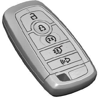
Passive Key

The passive key operates the power locks and the remote start system. The passive key must be in your vehicle to use the push button start.
Note: You may not be able to shift out of park (P) unless the passive key is inside your vehicle.
