Lincoln Aviator: Lighting / Autolamps and Instrument Lighting Dimmer
Autolamps
WARNING: The system does not relieve you of your responsibility to drive with due care and attention. You may need to override the system if it does not turn the headlamps on in low visibility conditions, for example daytime fog.
Autolamps turn the headlamps on in low light situations or when the wipers operate.
 Switch the lighting control to
the
autolamps position.
Note: The lighting control defaults to autolamps each time you switch your vehicle on.
The headlamps remain on for a period of time after you switch the ignition off. Use the touchscreen to adjust the period of time that the headlamps remain on.
Note: If you switch the autolamps on, you cannot switch the high beams on until the system turns the low beams on.
Windshield Wiper Activated Headlamps
When you switch the autolamps on, the headlamps turn on within 10 seconds of switching the wipers on. They turn off approximately 60 seconds after you switch the windshield wipers off.
The headlamps do not turn on with the wipers:
- During a single wipe.
- When using the windshield washers.
- If the wipers are in intermittent mode.
Note: If you switch the autolamps and the autowipers on, the headlamps turn on when the windshield wipers continuously operate.
Instrument Lighting Dimmer
The instrument lighting dimmer buttons are on the lighting control.

 Repeatedly press one of the
buttons to adjust the brightnes
 Lighting Control
Lighting Control Selections
Press the toggle switch upward or downward
to make a selection.
Note: An indicator illuminates next to the
active selection...
 Headlamp Exit Delay
After you switch the ignition off, you can
switch the headlamps on by pulling the
direction indicator lever toward you. You will
hear a short tone. The headlamps will switch
off automatically after three minutes with any
door open or 30 seconds after the last door
has been closed...
Other information:
Lincoln Aviator 2020-2026 Service Manual: Removal and Installation - Water Drain Panel
Special Tool(s) / General Equipment Resistance Spotwelding Equipment 8 mm Drill Bit MIG/MAG Welding Equipment Spot Weld Drill Bit Locking Pliers Materials Name Specification Flexible Foam Repair3M™ 08463, LORD Fusor® 121 - Removal WARNING: Electric vehicles damaged by a crash may have compromised high voltage safety systems and present a potential high voltage electrical shock hazard...
Lincoln Aviator 2020-2026 Service Manual: Removal and Installation - Bluetooth Rear Interior Antenna
Special Tool(s) / General Equipment Interior Trim Remover Removal NOTE: Left had side shown, right hand side similar. Remove the loadspace trim panel. Refer to: Loadspace Trim Panel (501-05 Interior Trim and Ornamentation, Removal and Installation)...
Categories
- Manuals Home
- Lincoln Aviator Owners Manual
- Lincoln Aviator Service Manual
- Changing the Front Wiper Blades - Vehicles With: Heated Wiper Blades
- USB Port and Power Point Locations
- Disabling Auto-Start-Stop
- New on site
- Most important about car
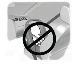
Children and Airbags
WARNING: Airbags can kill or injure a child in a child restraint. Never place a rear-facing child restraint in front of an active airbag. If you must use a forward-facing child restraint in the front seat, move the seat upon which the child restraint is installed all the way back.

