
Lincoln Aviator 2020-2026 Owners Manual / Lighting
Lincoln Aviator: Lighting
- General Information
- Lighting Control
- Autolamps and Instrument Lighting Dimmer
- Headlamp Exit Delay
- Daytime Running Lamps - Vehicles With: Configurable Daytime Running Lamps
- Daytime Running Lamps - Vehicles With: Daytime Running Lamps (DRL). Front Fog Lamps
- Adaptive Headlamps
- Direction Indicators
- Welcome Lighting
- Interior Lamps
- Ambient Lighting (If equipped)
 Rear Window Wiper and Washers
Rear Window Wiper
Intermittent wipe.
Continuous wipe.
Rear window wiper off.
Depending on your vehicle, when you switch
on the front wipers and move the gearshift
lever to reverse (R), the rear intermittent wipe
may turn on...
 General Information
Condensation in the Exterior Front Lamps and Rear Lamps
Exterior front lamps and rear lamps have
vents to accommodate normal changes in
air pressure...
Other information:
Lincoln Aviator 2020-2026 Service Manual: Removal and Installation - Subwoofer Speaker
Removal NOTE: Removal steps in this procedure may contain installation details. All vehicles Remove the LH loadspace trim panel. Refer to: Loadspace Trim Panel (501-05 Interior Trim and Ornamentation, Removal and Installation). Vehicles not equipped with Harmon® audio systems Position the subwoofer assembly to access rear connectors...
Lincoln Aviator 2020-2026 Service Manual: Removal and Installation - Brake Disc Shield
Removal NOTE: Removal steps in this procedure may contain installation details. Remove the brake disc. Refer to: Brake Disc (206-03 Front Disc Brake, Removal and Installation). Remove the 3 bolts and the brake disc shield...
Categories
- Manuals Home
- Lincoln Aviator Owners Manual
- Lincoln Aviator Service Manual
- Wireless Accessory Charger (If Equipped)
- Child Safety Locks
- Interior Lamps
- New on site
- Most important about car
Adjusting the Steering Wheel - Vehicles With: Manual Adjustable Steering Column
WARNING: Do not adjust the steering wheel when your vehicle is moving.
Note: Make sure that you are sitting in the correct position.
Unlock the steering column. Adjust the steering wheel to the desired position.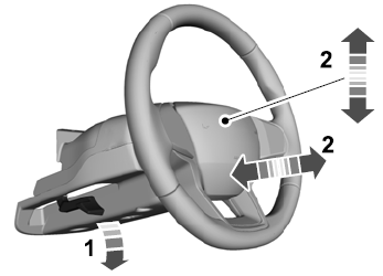

Copyright © 2026 www.liaviator2.com