Lincoln Aviator: Rear Climate Control / Description and Operation - Rear Climate Control - Overview
Overview
The rear climate control system has controls selection located in the rear of the floor console and the components located in the right rear quarter panel by the D pillar. The temperature and controls breakdown for the HVAC system is as follows, first row driver, first row passenger, second row seating temperature and third row seating temperature.
The rear climate control system is standard equipment. The rear climate control system operation is determined by the settings on the FCIMB control panel selection, the FDIM, the rear non touch screen RHVAC control panel or rear touch screen RACM control panel selection.
Both the rear non touch screen RHVAC control panel or rear touch screen RACM allow rear climate operation and control. They include a power on and off selection, a fan speed control selection, temperature control selection, air distribution control selection, and a rear climate control lock.
Through a setting in the RACM the rear (third row) climate control system can be linked with the second row climate system to have simultaneous control for both rows.
The rear system air can be cooled below interior air temperature only when A/C compressor operation has been requested by the settings of the climate control assembly of the FCIMB control panel or FDIM. The rear climate control system air can be heated at any time.
 Description and Operation - Rear Climate Control - System Operation and Component Description
System Operation
System Diagram
Item
Description
1
HVAC control module
2
Rear air distribution door actuator
3
Rear temperature door actuator
4
Rear blower motor relay
5
Rear blower motor speed control
6
Rear blower motor
7
Rear air discharge temperature sensor
8
Rear temperature sensor - Second Row
9
Rear footwell air discharge temperature sensor
10
Rear temperature sensor - Third Row
11
IPC
12
GWM
13
FCIMB
14
RACM (Rear Touch screen)
15
APIM ( FDIM Touch Screen)
16
RHVAC control module (Rear Non touch screen)
Network Message Charts
Module Network Input Messages - APIM
Broadcast Message
Originating Module
Message Purpose
Climate control button status
HVAC control module
This message contains the HVAC climate control settings for the touch screen display...
Other information:
Lincoln Aviator 2020-2026 Service Manual: Removal and Installation - Rear Temperature Sensor - Vehicles With: Third Row Seats
Removal NOTE: Removal steps in this procedure may contain installation details. Lower the headliner. Refer to: Headliner - Lowering (501-05 Interior Trim and Ornamentation, Removal and Installation). Remove the rear temperature sensor...
Lincoln Aviator 2020-2026 Service Manual: Description and Operation - Front Suspension - Overview
Overview The RWD front suspension consists of the following components: Front and rear lower arms Rear lower arm ball joints Stabilizer bar, bushings and links Ride height sensors (Vehicles with Continuously Controlled Damping (CCD) Suspension) Passive or dynamically controlled shock absorber and spring assembly (Continuously Controlled Damping (CCD)) Upper control arms Wheel bearings and wheel hubs Wheel knuckles Wheel studs The front suspension uses a double ball joint short long arm suspension system...
Categories
- Manuals Home
- Lincoln Aviator Owners Manual
- Lincoln Aviator Service Manual
- USB Port and Power Point Locations
- Opening and Closing the Hood
- Description and Operation - Body and Frame
- New on site
- Most important about car
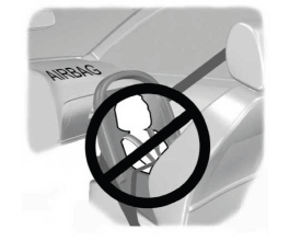
Children and Airbags
WARNING: Airbags can kill or injure a child in a child restraint. Never place a rear-facing child restraint in front of an active airbag. If you must use a forward-facing child restraint in the front seat, move the seat upon which the child restraint is installed all the way back.


