
Lincoln Aviator: Rear Climate Control / Description and Operation - Rear Climate Control - System Operation and Component Description
System Operation
System Diagram
.jpg)
.jpg)
| Item | Description |
|---|---|
| 1 | HVAC control module |
| 2 | Rear air distribution door actuator |
| 3 | Rear temperature door actuator |
| 4 | Rear blower motor relay |
| 5 | Rear blower motor speed control |
| 6 | Rear blower motor |
| 7 | Rear air discharge temperature sensor |
| 8 | Rear temperature sensor - Second Row |
| 9 | Rear footwell air discharge temperature sensor |
| 10 | Rear temperature sensor - Third Row |
| 11 | IPC |
| 12 | GWM |
| 13 | FCIMB |
| 14 | RACM (Rear Touch screen) |
| 15 | APIM ( FDIM Touch Screen) |
| 16 | RHVAC control module (Rear Non touch screen) |
Network Message Charts
Module Network Input Messages - APIM
| Broadcast Message | Originating Module | Message Purpose |
|---|---|---|
| Climate control button status | HVAC control module | This message contains the HVAC climate control settings for the touch screen display. |
Module Network Input Messages - FCIMB
| Broadcast Message | Originating Module | Message Purpose |
|---|---|---|
| Climate control touch screen and voice requests | APIM | This message contains both the climate control system voice commands as well as all climate control system touch screen inputs. |
| Climate control status | HVAC control module | This message contains the HVAC mode status for the mode indicators. |
Module Network Input Messages - HVAC Control Module
| Broadcast Message | Originating Module | Message Purpose |
|---|---|---|
| Climate control requests (gateway) | FCIMB | This message contains all climate control system controls requests except blower motor speed. |
| Climate control requests (gateway) | FCIMB | This message contains the climate control system controls request for blower motor speed. |
| HVAC rear blower indicator status | HVAC | This message contains the rear non touch screen RHVAC control module or rear touch screen RACM blower motor setting for the touch screen display. |
Rear Climate Controls
For diagnosis and testing of the rear climate control system,
Refer to: Climate Control System (412-00 Climate Control System - General Information, Diagnosis and Testing).
The rear climate control system operation is determined by the settings on the front HVAC control panel selection, FDIM or from the rear climate control panel, known as the rear non touch screen RHVAC control module or rear touch screen RACM. Messages are sent to the HVAC control module over the CAN. The non touch screen RHVAC control module communicates on the MS-CAN. The rear touch screen RACM communicates on the HS-CAN3. The rear climate control components are hard wired to the HVAC control module. Air is cooled and dehumidified by the rear A/C evaporator core only if the front (main) climate control system is operating in a mode that requires A/C compressor operation.
Vehicles equipped with a rear non touch screen RHVAC control module, the second row and rear (third row) climate controls are controlled as one climate zone. When the climate control settings are selected to heat or cool, both rows are changed as one climate zone.
Vehicles equipped with a rear touch screen RACM, the second row and rear (third row) climate controls are independently controlled as two separate climate zones. When the climate control settings are selected the two zones are heated or cooled as a climate control zone for the second row and a separate climate control zone for the rear (third row). Through a setting in the rear touch screen RACM, the two zones can also be linked together.
The command for warm or cold air to the rear non touch screen RHVAC control module or rear touch screen RACM may make a difference in the rear air delivery vents. The commands that are directly inputted from the RHVAC control module or rear touch screen RACM to the rear air delivery and temperature system may work better than the commands that are directly inputted from the front HVAC system.
For rear climate control access information through FDIM Sync™ 3 or the front HVAC control module refer to Owner's Literature.
Rear Climate Controls - FCIMB
The customer interface from the front (main) FCIMB panel for the second climate system consists of the following selections:
- Rear passenger temperature control
- Rear climate control lock
- Rear passenger power
- Rear fan speed control
For illustrations and rear climate control button operation information, refer to the Owner's Literature.
Rear Climate Controls - Front FDIM Touchscreen
The customer interface from the touchscreen has access to the rear climate control system. In the lower right of the main touchscreen, touch Climate. On the climate screen, touch Rear from the lower right corner. Rear climate control settings appear at the bottom of the screen:
- Touch the power icon to turn the rear climate control functions off and on.
- Touch Rear Control to allow the rear seat passengers to adjust the rear climate settings. Touch it again to prevent the rear seat passengers from adjusting the settings. Rear Control automatically turns off when you use the touchscreen to adjust the rear climate settings.
- Touch + or – to adjust the temperature.
- To adjust fan speed, touch + or – next to the fan icon.
- Touch Rear again to close the rear controls. Closing the rear climate control functions does not affect their current settings.
For illustrations and rear climate control button operation information, refer to the Owner's Literature.
Rear Climate Controls - Center Console
The customer interface from the rear non touch screen RHVAC control panel or rear touch screen RACM control panel for the rear climate control system consist of the following selections.
- Rear (third row) passenger temperature control
- Rear (third row) climate control lock
- Rear (third row) passenger power
- Rear (third row) fan speed control
- Rear (third row) linked with second row climate control
For illustrations and second climate control button operation information, refer to the Owner's Literature.
Control System Logic
The rear (third row) climate control can be controlled by either the main front HVAC controls or the center console controls. When a selection is made on the rear climate control panel, known as the rear non touch screen RHVAC control module or rear touch screen RACM, a message is sent to the HVAC control module over the CAN. The non touch screen RHVAC control module communicates on the MS-CAN. The rear touch screen RACM communicates on the HS-CAN3.
Vehicles equipped with a rear non touch screen RHVAC control module, the second row and rear (third row) climate controls are controlled as one climate zone. When the climate control settings are selected to heat or cool, both rows are changed as one climate zone.
Vehicles equipped with a rear touch screen RACM, the second row and rear (third row) climate controls are independently controlled as two separate climate zones. When the climate control settings are selected the two zones are heated or cooled as a climate control zone for the second row and a climate control zone for the rear (third row). Through a setting in the rear touch screen RACM, the two zones can also be linked together.
Air Handling
The rear climate control system has the following features:
- The driver has primary control of the rear climate control system or can transfer control to the rear passenger control panel.
- The rear blower motor recirculates the air inside the vehicle. Outside air is not available to the rear system.
- The rear temperature door and the rear air distribution door are controlled by electric actuator motors.
- Movement of the rear temperature control between cool and warm causes a corresponding movement of the rear temperature door to mix air flowing through and around the rear heater core.
- Movement of the rear mode control between PANEL and FLOOR causes a corresponding movement of the rear air distribution door to direct airflow between the panel (upper side trim panel) registers and the floor duct.
- Airflow is directed to the passengers through adjustable registers. The heater floor duct supplies air to a fixed register, which is integral to the side trim panel.
The HVAC control module sends a PWM signal to the rear blower motor speed control to control the blower speed. The rear blower motor speed control provides variable ground feed for the blower motor. A delay function provides a gradual increase or decrease in blower motor speed under all conditions.
Component Description
Component Description
Rear Air Discharge Temperature Sensors
There are 2 rear air discharge temperature sensors in the rear (third row) climate control system:
- The rear footwell air discharge temperature sensor is located within the right rear quarter panel lower air duct.
- The rear air discharge temperature sensor is located within the right rear quarter panel upper air duct.
The rear air discharge temperature sensors contain a thermistor and are inputs to the HVAC control module. The sensors vary their resistance with the temperature. As the temperature rises, the resistance falls. As the temperature falls, the resistance rises. The HVAC control module uses the sensor information to maintain the desired temperature of the passenger cabin air.
Rear Air Distribution Door Actuator
The rear air distribution door actuator is located within the right rear quarter panel by the D pillar. The rear air distribution door actuator moves the rear air distribution door on command from the HVAC control module based on input from either the front or rear climate controls.
The rear air distribution door actuator contains a reversible electric motor and potentiometer. The potentiometer allows the HVAC control module to monitor the position of the rear air distribution door. The potentiometer circuit consists of a 5-volt reference signal connected to one end of a variable resistor, and a signal ground connected to the other. A signal circuit is connected to a contact wiper, which is driven along the variable resistor by the actuator shaft. The signal to the HVAC control module from the contact wiper indicates the position of the rear air distribution door.
RACM
The
rear touchscreen is used to adjust the rear (second and third row)
climate control and other functions. It communicates these inputs over
the HS-CAN3. For more information on the RACM,
Refer to: Information and Entertainment System - System Operation and Component Description (415-00 Information and Entertainment System - General Information, Description and Operation).
Rear Blower Motor
The rear blower motor is located in the right rear panel by the D pillar. The rear blower motor is a variable speed motor that pulls air from the vehicle interior and forces it through the rear climate control housing and the rear climate control air distribution ducts.
Rear Blower Motor Speed Control
The rear blower motor speed control is located in the right rear panel by the D pillar. The rear blower motor speed control is a solid-state switch that uses a PWM signal from the HVAC control module to determine the desired rear blower motor speed and varies the ground feed for the rear blower motor to control the speed. A delay function provides a gradual increase or decrease in rear blower motor speed under all conditions.
Rear Climate Control Housing
The rear climate control housing is located in the right rear panel by the D pillar. The rear climate control housing directs airflow from the rear blower motor through the rear evaporator core and rear heater core. All airflow from the rear blower motor passes through the rear evaporator core. The airflow is then distributed to the selected outlet by the airflow mode doors.
Rear Evaporator
The rear evaporator core is an aluminum plate-and-fin type heat exchanger and is located in the rear climate control housing. A mixture of liquid refrigerant and oil enters the rear evaporator core through the rear evaporator core inlet tube and continues out of the rear evaporator core through the rear evaporator core outlet tube as a vapor. During A/C compressor operation, airflow from the rear blower motor is cooled and dehumidified as it flows through the rear evaporator core fins.
Rear Heater Core
The rear heater core consists of fins and tubes arranged to extract heat from the engine coolant and transfer the heat to air passing through the rear climate control housing.
Rear A/C - Heater Inlet and Outlet Lines
The rear climate control system A/C and heater inlet and outlet lines that are all part of an assembly that runs from front to back on the vehicle and are bracketed together and fastened to the underbody of the vehicle.
RHVAC Control Module
The rear non touch screen RHVAC control module is used by the rear vehicle occupants to request changes to the rear climate control system (second and third row). The requests are sent to the HVAC control module over the MS-CAN.
Rear Temperature Door Actuator
The rear temperature door actuator is located within the right rear quarter panel by the D pillar. The rear temperature door actuator moves the rear temperature door on command from the HVAC control module based on input from either the front or rear climate controls.
The rear temperature door actuator contains a reversible electric motor and potentiometer. The potentiometer allows the HVAC control module to monitor the position of the rear temperature door. The potentiometer circuit consists of a 5-volt reference signal connected to one end of a variable resistor, and a signal ground connected to the other. A signal circuit is connected to a contact wiper, which is driven along the variable resistor by the actuator shaft. The signal to the HVAC control module from the contact wiper indicates the position of the rear temperature door.
Rear temperature sensor - vehicles with: second row seats
The rear temperature sensor - vehicles with: second row seats is located in the headliner above the second row seating in the microphone bezel assembly. The rear temperature sensor contains a thermistor which separately measures the in-vehicle air temperature, then sends those readings to the HVAC control module. The HVAC control module may adjust the rear climate control system based on the second row seat rear temperature sensor information to maintain the desired temperature of the rear passenger cabin air.
Rear temperature sensor - vehicles with: third row seats
The rear temperature sensor - vehicles with: third row seats is located in the headliner above the third row seating in the microphone bezel assembly. The rear temperature sensor contains a thermistor which separately measures the in-vehicle air temperature, then sends those readings to the HVAC control module. The HVAC control module may adjust the rear climate control system based on the third row seat rear temperature sensor information to maintain the desired temperature of the rear passenger cabin air.
Rear Thermostatic Expansion Valve (TXV)
The rear Thermostatic Expansion Valve (TXV) is located at the rear evaporator core inlet and outlet tubes. The rear Thermostatic Expansion Valve (TXV) provides a restriction to the flow of refrigerant and separates the low-pressure and high-pressure sides of the rear refrigerant system. Refrigerant entering and exiting the rear evaporator core passes through the rear Thermostatic Expansion Valve (TXV) through 2 separate flow paths. An internal temperature sensing bulb senses the temperature of the refrigerant flowing out of the rear evaporator core and adjusts an internal pin-type valve to meter the refrigerant flow into the rear evaporator core. The internal pin-type valve decreases the amount of refrigerant entering the rear evaporator core at lower temperatures and increases the amount of refrigerant entering the rear evaporator core at higher temperatures.
 Description and Operation - Rear Climate Control - Overview
Overview
The
rear climate control system has controls selection located in the rear
of the floor console and the components located in the right rear
quarter panel by the D pillar...
 Removal and Installation - Rear Air Distribution Door Actuator
Removal
NOTE:
Removal steps in this procedure may contain installation details.
Remove the RH loadspace trim panel.
Refer to: Loadspace Trim Panel (501-05 Interior Trim and Ornamentation, Removal and Installation)...
Other information:
Lincoln Aviator 2020-2026 Owners Manual: All-wheel drive system (if equipped)
WARNING: Do not become overconfident in the ability of four-wheel drive vehicles. Although a four-wheel drive vehicle may accelerate better than a two-wheel drive vehicle in low traction situations, it won't stop any faster than two-wheel drive vehicles...
Lincoln Aviator 2020-2026 Service Manual: Diagnosis and Testing - Vehicle Dynamic Suspension - Vehicles With: Air Suspension
Diagnostic Trouble Code (DTC) Chart Diagnostics in this manual assume a certain skill level and knowledge of Ford-specific diagnostic practices. REFER to: Diagnostic Methods (100-00 General Information, Description and Operation). Diagnostic Trouble Code Chart Module DTC Description Action SUMA B1041:52 Levelling Control: Not Activated GO to Pinpoint Test W SUMA C1043:00 Pressure Decrease Too Slow From Reservoir: No Sub Type Information GO to Pinpoint Test M SUMA C104C:11 Left Rear Spring Rate Valve: Circuit Short To Ground GO to Pinpoint Test E SUMA C104C:12 Left Rear Spring Rate Valve: Circuit Short To Battery GO to Pinpoint Test E SUMA C104C:13 Left Rear Spring Rate Valve: Circuit Open GO to Pinpoint Test E SUMA C104C:1A Left Rear Spring Rate Valve: Circuit Resistance Below Threshold GO to Pinpoint Test E SUMA C104C:1F Left Rear Spring Rate Valve: Circuit Intermittent GO to Pinpoint Test E SUMA C104D:11 Right Front Spring Rate Valve: Circuit Short To Ground GO to Pinpoint Test D SUMA C104D:12 Right Front Spring Rate Valve: Circuit Short To Battery GO to Pinpoint Test D SUMA C104D:13 Right Front Spring Rate Valve: Circuit Open GO to Pinpoint Test D SUMA C104D:1A Right Front Spring Rate Valve: Circuit Resistance Below Threshold GO to Pinpoint Test D SUMA C104D:1F Right Front Spring Rate Valve: Circuit Intermittent GO to Pinpoint Test D SUMA C104E:11 Right Rear Spring Rate Valve: Circuit Short To Ground GO to Pinpoint Test F SUMA C104E:12 Right Rear Spring Rate Valve: Circuit Short To Battery GO to Pinpoint Test F SUMA C104E:13 Right Rear Spring Rate Valve: Circuit Open GO to Pinpoint Test F SUMA C104E:1A Right Rear Spring Rate Valve: Circuit Resistance Below Threshold GO to Pinpoint Test F SUMA C104E:1F Right Rear Spring Rate Valve: Circuit Intermittent GO to Pinpoint Test F SUMA C104F:11 Left Front Spring Rate Valve: Circuit Short To Ground GO to Pinpoint Test C SUMA C104F:12 Left Front Spring Rate Valve: Circuit Short To Battery GO to Pinpoint Test C SUMA C104F:13 Left Front Spring Rate Valve: Circuit Open GO to Pinpoint Test C SUMA C104F:1A Left Front Spring Rate Valve: Circuit Resistance Below Threshold GO to Pinpoint Test C SUMA C104F:1F Left Front Spring Rate Valve: Circuit Intermittent GO to Pinpoint Test C SUMA C1124:07 Height Sensor(s): Mechanical Failures GO to Pinpoint Test G SUMA C1124:11 Height Sensor(s): Circuit Short To Ground GO to Pinpoint Test H SUMA C1124:12 Height Sensor(s): Circuit Short To Battery GO to Pinpoint Test H SUMA C1124:54 Height Sensor(s): Missing Calibration GO to Pinpoint Test U SUMA C1A03:2A Left Front Height Sensor: Stuck in Range GO to Pinpoint Test I SUMA C1A03:34 Left Front Height Sensor: Signal High Time Less Than Minimum GO to Pinpoint Test I SUMA C1A03:35 Left Front Height Sensor: Signal High Time Greater Than Maximum GO to Pinpoint Test I SUMA C1A03:36 Left Front Height Sensor: Signal Frequency Too Low GO to Pinpoint Test I SUMA C1A03:37 Left Front Height Sensor: Signal Frequency Too High GO to Pinpoint Test I SUMA C1A03:84 Left Front Height Sensor: Signal Below Allowable Range GO to Pinpoint Test I SUMA C1A03:85 Left Front Height Sensor: Signal Above Allowable Range GO to Pinpoint Test I SUMA C1A04:2A Right Front Height Sensor: Stuck in Range GO to Pinpoint Test J SUMA C1A04:34 Right Front Height Sensor: Signal High Time Less Than Minimum GO to Pinpoint Test J SUMA C1A04:35 Right Front Height Sensor: Signal High Time Greater Than Maximum GO to Pinpoint Test J SUMA C1A04:36 Right Front Height Sensor: Signal Frequency Too Low GO to Pinpoint Test J SUMA C1A04:37 Right Front Height Sensor: Signal Frequency Too High GO to Pinpoint Test J SUMA C1A04:84 Right Front Height Sensor: Signal Below Allowable Range GO to Pinpoint Test J SUMA C1A04:85 Right Front Height Sensor: Signal Above Allowable Range GO to Pinpoint Test J SUMA C1A05:2A Left Rear Height Sensor: Stuck in Range GO to Pinpoint Test K SUMA C1A05:34 Left Rear Height Sensor: Signal High Time Less Than Minimum GO to Pinpoint Test K SUMA C1A05:35 Left Rear Height Sensor: Signal High Time Greater Than Maximum GO to Pinpoint Test K SUMA C1A05:36 Left Rear Height Sensor: Signal Frequency Too Low GO to Pinpoint Test K SUMA C1A05:37 Left Rear Height Sensor: Signal Frequency Too High GO to Pinpoint Test K SUMA C1A05:84 Left Rear Height Sensor: Signal Below Allowable Range GO to Pinpoint Test K SUMA C1A05:85 Left Rear Height Sensor: Signal Above Allowable Range GO to Pinpoint Test K SUMA C1A06:2A Right Rear Height Sensor: Stuck in Range GO to Pinpoint Test L SUMA C1A06:34 Right Rear Height Sensor: Signal High Time Less Than Minimum GO to Pinpoint Test L SUMA C1A06:35 Right Rear Height Sensor: Signal High Time Greater Than Maximum GO to Pinpoint Test L SUMA C1A06:36 Right Rear Height Sensor: Signal Frequency Too Low GO to Pinpoint Test L SUMA C1A06:37 Right Rear Height Sensor: Signal Frequency Too High GO to Pinpoint Test L SUMA C1A06:84 Right Rear Height Sensor: Signal Below Allowable Range GO to Pinpoint Test L SUMA C1A06:85 Right Rear Height Sensor: Signal Above Allowable Range GO to Pinpoint Test L SUMA C1A20:00 Pressure Increase Too Slow When Filling Reservoir: No Sub Type Information GO to Pinpoint Test M SUMA C1A27:09 Compressor: Component Failures GO to Pinpoint Test N SUMA C1A27:63 Compressor: Circuit/Component Protection Time-Out GO to Pinpoint Test N SUMA C1A27:98 Compressor: Component Or System Over Temperature GO to Pinpoint Test N SUMA C1A27:99 Compressor: Exceeded Learning Limit GO to Pinpoint Test N SUMA C1A31:63 Left Front Corner Valve: Circuit/Component Protection Time-Out GO to Pinpoint Test AD SUMA C1A32:63 Right Front Corner Valve: Circuit/Component Protection Time-Out GO to Pinpoint Test AD SUMA C1A33:63 Left Rear Corner Valve: Circuit/Component Protection Time-Out GO to Pinpoint Test AD SUMA C1A34:63 Right Rear Corner Valve: Circuit/Component Protection Time-Out GO to Pinpoint Test AD SUMA C1A36:63 Exhaust Valve: Circuit/Component Protection Time-Out GO to Pinpoint Test AD SUMA U0100:87 Lost Communication With ECM / PCM: Missing Message GO to Pinpoint Test O SUMA U0121:87 Lost Communication With Anti-Lock Brake System (ABS) Control Module: Missing Message GO to Pinpoint Test P SUMA U0122:87 Lost Communication With Vehicle Dynamics Control Module: Missing Message GO to Pinpoint Test Q SUMA U0131:87 Lost Communication With Power Steering Control Module "A": Missing Message GO to Pinpoint Test R SUMA U0140:87 Lost Communication With Body Control Module: Missing Message GO to Pinpoint Test S SUMA U0146:87 Lost Communication With Serial Data Gateway "A": Missing Message GO to Pinpoint Test T SUMA U0401:00 Invalid Data Received from ECM/PCM A: No Sub Type Information GO to Pinpoint Test X SUMA U0415:00 Invalid Data Received from Anti-Lock Brake System (ABS) Control Module "A": No Sub Type Information GO to Pinpoint Test Y SUMA U0416:00 Invalid Data Received From Vehicle Dynamics Control Module: No Sub Type Information GO to Pinpoint Test Z SUMA U0420:00 Invalid Data Received from Power Steering Control Module "A": No Sub Type Information GO to Pinpoint Test AA SUMA U0422:00 Invalid Data Received From Body Control Module: No Sub Type Information GO to Pinpoint Test AB SUMA U0447:00 Invalid Data Received From Serial Data Gateway "A": No Sub Type Information GO to Pinpoint Test AC SUMA U2100:00 Initial Configuration Not Complete: No Sub Type Information GO to Pinpoint Test V SUMA U2100:56 Initial Configuration Not Complete: Invalid/Incompatible Configuration GO to Pinpoint Test V SUMA U3000:04 Control Module: System Internal Failures GO to Pinpoint Test V SUMA U3000:45 Control Module: Program Memory Failure GO to Pinpoint Test V SUMA U3000:46 Control Module: Calibration/Parameter Memory Failure GO to Pinpoint Test V SUMA U3000:47 Control Module: Watchdog/Safety µC Failure GO to Pinpoint Test V SUMA U3000:48 Control Module: Supervision Software Failure GO to Pinpoint Test V SUMA U3003:16 Battery Voltage: Circuit Voltage Below Threshold GO to Pinpoint Test A SUMA U3003:17 Battery Voltage: Circuit Voltage Above Threshold GO to Pinpoint Test B Symptom Chart Symptom Chart: Vehicle Dynamic Suspension Diagnostics in this manual assume a certain skill level and knowledge of Ford-specific diagnostic practices...
Categories
- Manuals Home
- Lincoln Aviator Owners Manual
- Lincoln Aviator Service Manual
- Remove and Reinstall the Battery
- Changing the Front Wiper Blades - Vehicles With: Heated Wiper Blades
- Disabling Auto-Start-Stop
- New on site
- Most important about car
Locking and Unlocking the Doors from Inside
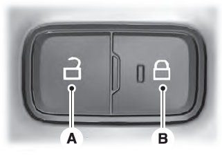
Locking the Doors
Press the lock switch on the door interior trim panel. The doors can no longer be released using the exterior door handle switches and the luggage compartment locks.
