
Lincoln Aviator: Navigation (If Equipped) / Michelin Travel Guide (If Equipped)

The Michelin travel guide is a service which provides additional information about certain places of interest, for example restaurants, hotels and tourist sites. Points of interest that have Michelin travel guide information display a button to show you more information. Push the button to see the additional information. If you have paired your phone with the system, you can press the phone button to directly establish a call with the selected point of interest.

    SiriusXM Traffic and Travel Link (If Equipped)

    SiriusXM Traffic and Travel Link is available on vehicles equipped with navigation and only in select markets. You must activate and subscribe to receive SiriusXM Traffic and Travel Link information...

    Navigation Map Accuracy and Updates

    HERE is the digital map provider for the navigation application. If you find map data errors, you may report them directly to HERE by going to www.here...

    Other information:

    Lincoln Aviator 2020-2026 Service Manual: General Procedures - Refrigerant Oil Adding - Hybrid Electric Vehicle (HEV), Vehicles With: R134A Refrigerant


    Special Tool(s) / General Equipment Air Conditioning Service Unit Check NOTICE: Motorcraft® Electric A/C Compressor Oil (YN-32) only must be used as a refrigerant system lubricant for High Voltage Battery Electric vehicles. Addition of any oil other than Motorcraft® Electric A/C Compressor Oil (YN-32) to the High Voltage Battery Electric vehicle refrigerant system will damage the electric A/C compressor and contaminate the refrigerant system...

    Lincoln Aviator 2020-2026 Service Manual: Diagnosis and Testing - Vehicle Dynamic Suspension


    Diagnostic Trouble Code (DTC) Chart Diagnostics in this manual assume a certain skill level and knowledge of Ford-specific diagnostic practices. REFER to: Diagnostic Methods (100-00 General Information, Description and Operation).   Diagnostic Trouble Code Chart Module   DTC Description Action   VDM C110C:11 Left Front Damper Solenoid: Circuit Short to Ground   GO to Pinpoint Test D   VDM C110C:12 Left Front Damper Solenoid: Circuit Short to Battery   GO to Pinpoint Test D   VDM C110C:13 Left Front Damper Solenoid: Circuit Open   GO to Pinpoint Test D   VDM C110C:64 Left Front Damper Solenoid:Signal Plausibility Failure   GO to Pinpoint Test D   VDM C110D:11 Right Front Damper Solenoid: Circuit Short to Ground   GO to Pinpoint Test E   VDM C110D:12 Right Front Damper Solenoid: Circuit Short to Battery   GO to Pinpoint Test E   VDM C110D:13 Right Front Damper Solenoid: Circuit Open   GO to Pinpoint Test E   VDM C110D:64 Right Front Damper Solenoid:Signal Plausibility Failure   GO to Pinpoint Test E   VDM C110E:11 Left Rear Damper Solenoid: Circuit Short to Ground   GO to Pinpoint Test F   VDM C110E:12 Left Rear Damper Solenoid: Circuit Short to Battery   GO to Pinpoint Test F   VDM C110E:13 Left Rear Damper Solenoid: Circuit Open   GO to Pinpoint Test F   VDM C110E:64 Left Rear Damper Solenoid:Signal Plausibility Failure   GO to Pinpoint Test F   VDM C110F:11 Right Rear Damper Solenoid: Circuit Short to Ground   GO to Pinpoint Test G   VDM C110F:12 Right Rear Damper Solenoid: Circuit Short to Battery   GO to Pinpoint Test G   VDM C110F:13 Right Rear Damper Solenoid: Circuit Open   GO to Pinpoint Test G   VDM C110F:64 Right Rear Damper Solenoid:Signal Plausibility Failure   GO to Pinpoint Test G   VDM C1124:55 Height Sensor(s):Not Configured   GO to Pinpoint Test U   VDM C1124:56 Height Sensor(s):Invalid/Incompatible Configuration   GO to Pinpoint Test U   VDM C1A03:11 Left Front Height Sensor: Circuit Short to Ground   GO to Pinpoint Test H   VDM C1A03:12 Left Front Height Sensor: Circuit Short to Battery   GO to Pinpoint Test H   VDM C1A03:29 Left Front Height Sensor:Signal Invalid   GO to Pinpoint Test H   VDM C1A03:64 Left Front Height Sensor:Signal Plausibility Failure   GO to Pinpoint Test T   VDM C1A04:11 Right Front Height Sensor: Circuit Short to Ground   GO to Pinpoint Test I   VDM C1A04:12 Right Front Height Sensor: Circuit Short to Battery   GO to Pinpoint Test I   VDM C1A04:29 Right Front Height Sensor:Signal Invalid   GO to Pinpoint Test I   VDM C1A04:64 Right Front Height Sensor:Signal Plausibility Failure   GO to Pinpoint Test T   VDM C1A05:11 Left Rear Height Sensor: Circuit Short to Ground   GO to Pinpoint Test J   VDM C1A05:12 Left Rear Height Sensor: Circuit Short to Battery   GO to Pinpoint Test J   VDM C1A05:29 Left Rear Height Sensor:Signal Invalid   GO to Pinpoint Test J   VDM C1A05:64 Left Rear Height Sensor:Signal Plausibility Failure   GO to Pinpoint Test T   VDM C1A06:11 Right Rear Height Sensor: Circuit Short to Ground   GO to Pinpoint Test K   VDM C1A06:12 Right Rear Height Sensor: Circuit Short to Battery   GO to Pinpoint Test K   VDM C1A06:29 Right Rear Height Sensor:Signal Invalid   GO to Pinpoint Test K   VDM C1A06:64 Right Rear Height Sensor:Signal Plausibility Failure   GO to Pinpoint Test T   VDM P1758:19 Pressure Solenoid Control System Incorrect Current: Circuit Current Above Threshold   GO to Pinpoint Test C   VDM U0100:87 Lost Communication With ECM / PCM: Missing Message   GO to Pinpoint Test M   VDM U0121:87 Lost Communication With Anti-Lock Brake System (ABS) Control Module: Missing Message   GO to Pinpoint Test N   VDM U0131:87 Lost Communication With EPAS module: Missing Message   GO to Pinpoint Test O   VDM U0140:87 Lost Communication With Body Control Module: Missing Message   GO to Pinpoint Test P   VDM U0151:87 Lost Communication With Restraints Control Module: Missing Message   GO to Pinpoint Test Q   VDM U0164:87 Lost Communication With HVAC Control Module:Missing Message   GO to Pinpoint Test R   VDM U023A:87 Lost Communication With Image Processing Module A:Missing Message   GO to Pinpoint Test S   VDM U0401:00 Invalid Data Received from ECM/PCM A:No Sub Type Information   GO to Pinpoint Test W   VDM U0415:00 Invalid Data Received from Anti-Lock Brake System (ABS) Control Module "A":No Sub Type Information   GO to Pinpoint Test X   VDM U0420:00 Invalid Data Received from Power Steering Control Module "A":No Sub Type Information   GO to Pinpoint Test Y   VDM U0422:00 Invalid Data Received From Body Control Module:No Sub Type Information   GO to Pinpoint Test Z   VDM U0424:00 Invalid Data Received From HVAC Control Module:No Sub Type Information   GO to Pinpoint Test AA   VDM U0452:00 Invalid Data Received From Restraints Control Module:No Sub Type Information   GO to Pinpoint Test AB   VDM U053B:00 Invalid Data Received From Image Processing Module A:No Sub Type Information   GO to Pinpoint Test AC   VDM U1000:00 Solid State Driver Protection Active -Driver Disabled:No Sub Type Information   GO to Pinpoint Test V   VDM U200D:11 Control Module Output Power A: Circuit Short to Ground   GO to Pinpoint Test L   VDM U200D:12 Control Module Output Power A: Circuit Short to Battery   GO to Pinpoint Test L   VDM U200E:11 Control Module Output Power B: Circuit Short to Ground   GO to Pinpoint Test L   VDM U200E:12 Control Module Output Power B: Circuit Short to Battery   GO to Pinpoint Test L   VDM U200F:11 Control Module Output Power C:Circuit Short To Ground   GO to Pinpoint Test J   VDM U200F:12 Control Module Output Power C:Circuit Short To Battery   GO to Pinpoint Test J   VDM U201E:11 Control Module Output Power D:Circuit Short To Ground   GO to Pinpoint Test K   VDM U201E:12 Control Module Output Power D:Circuit Short To Battery   GO to Pinpoint Test K   VDM U2024:51 Control Module Cal-Config Data:Not Programmed   GO to Pinpoint Test V   VDM U2100:00 Initial Configuration Not Complete:No Sub Type Information   GO to Pinpoint Test V   VDM U2200:00 Control Module Configuration Memory Corrupt:No Sub Type Information   GO to Pinpoint Test V   VDM U3000:04 Control Module:System Internal Failures   GO to Pinpoint Test V   VDM U3000:49 Control Module:Internal Electronic Failure   GO to Pinpoint Test V   VDM U3003:16 Battery Voltage: Circuit Voltage Below Threshold   GO to Pinpoint Test A   VDM U3003:17 Battery Voltage: Circuit Voltage Above Threshold   GO to Pinpoint Test B Symptom Chart Symptom Chart: Vehicle Dynamic Suspension Diagnostics in this manual assume a certain skill level and knowledge of Ford-specific diagnostic practices...

    Categories

    Activating Intelligent Access

    The intelligent access key must be within 3 ft (1 m) of the door or luggage compartment you intend to lock or unlock.

    At a Door

    Electronic door handles are on each door. Gently depress the switch inside the exterior door handle to unlock and open the door. An unlock symbol illuminates on the door window trim indicating your vehicle is unlocked.
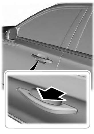
    Lincoln Aviator. Activating Intelligent Access

    read more

     
    Copyright © 2026 www.liaviator2.com