Lincoln Aviator 2020-2026 Service Manual / Chassis / Driveline / Rear Drive Axle/Differential / Removal and Installation - Differential Housing Cover
Lincoln Aviator: Rear Drive Axle/Differential / Removal and Installation - Differential Housing Cover
Materials
| Name | Specification |
|---|---|
| Motorcraft® Ultra Silicone Sealant TA-29 |
WSS-M4G323-A8 |
Removal
-
With the vehicle in NEUTRAL, position it on a hoist.
Refer to: Jacking and Lifting (100-02 Jacking and Lifting, Description and Operation).
-
Remove the rear axle assembly.
Refer to: Axle Assembly (205-02 Rear Drive Axle/Differential, Removal and Installation).
-
Remove the differential housing cover bolts and the cover.
.jpg) |
-
NOTE: Make sure the machined surfaces on the rear axle housing and the differential housing cover are clean and free of oil before installing the new silicone sealant. Cover the inside of the rear axle when cleaning the machined surface to prevent contamination.
Clean the gasket mating surfaces of the differential housing and the differential housing cover.
.jpg) |
Installation
-
NOTE: The differential housing cover must be installed within 15 minutes of application of the silicone, or new silicone must be applied. If possible, allow one hour before filling with lubricant to make sure the silicone has correctly cured.
NOTE: Care should be taken not to allow RTV sealant spillage in bowl of differential carrier.
Apply a new bead of sealant to the differential housing as shown.
Material: Motorcraft® Ultra Silicone Sealant / TA-29 (WSS-M4G323-A8)
.jpg) |
-
Install the differential housing cover and the differential housing cover bolts.
Torque: 33 lb.ft (45 Nm)
.jpg) |
-
Install the rear axle assembly.
Refer to: Axle Assembly (205-02 Rear Drive Axle/Differential, Removal and Installation).
 Removal and Installation - Differential Carrier
Special Tool(s) /
General Equipment
205-220Installer, Differential ShimTKIT-1985-FH
Copper Hammer
Removal
Remove the differential housing cover...
 Removal and Installation - Drive Pinion Seal
Special Tool(s) /
General Equipment
205-1061Installer, Pinion Seal 8.8
205-199
(T83T-3132-A1)
Installer, Spindle/Axle ShaftT83-4000-ATKIT-1983-FTKIT-1983-FLMTKIT-1983-FX
Flat Headed Screw Driver
Materials
Name
Specification
Motorcraft® Premium Long-Life GreaseXG-1-E1
ESA-M1C75-B
Removal
With the vehicle in NEUTRAL, position it on a hoist...
Other information:
Lincoln Aviator 2020-2026 Owners Manual: Changing a Road Wheel
WARNING: If the tire pressure monitor sensor becomes damaged it may not function. Note: You should only use tire sealants in roadside emergencies as they may cause damage to the tire pressure monitoring system sensor. Note: The tire pressure monitoring system indicator light illuminates when the spare tire is in use...
Lincoln Aviator 2020-2026 Owners Manual: How Temperature Affects Your Tire Pressure
The tire pressure monitoring system monitors tire pressure in each pneumatic tire. While driving in a normal manner, a typical passenger tire inflation pressure may increase about 2–4 psi (14–28 kPa) from a cold start situation. If the vehicle is stationary overnight with the outside temperature significantly lower than the daytime temperature, the tire pressure may decrease about 3 psi (21 kPa) for a drop of 30°F (17°C) in ambient temperature...
Categories
- Manuals Home
- Lincoln Aviator Owners Manual
- Lincoln Aviator Service Manual
- Opening and Closing the Hood
- Wireless Accessory Charger (If Equipped)
- Locking and Unlocking
- New on site
- Most important about car
Fastening the Seatbelts
The front outboard and rear safety restraints in the vehicle are combination lap and shoulder belts.
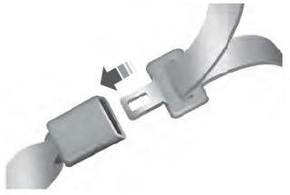
Insert the belt tongue into the proper buckle (the buckle closest to the direction the tongue is coming from) until you hear a snap and feel it latch. Make sure that you securely fasten the tongue in the buckle.
Copyright © 2026 www.liaviator2.com
