Lincoln Aviator: Supplemental Restraint System / Removal and Installation - Driver Knee Airbag
Removal
WARNING:
The following procedure prescribes critical repair steps
required for correct restraint system operation during a crash. Follow
all notes and steps carefully. Failure to follow step instructions may
result in incorrect operation of the restraint system and increases the
risk of serious personal injury or death in a crash.
NOTE:
Removal steps in this procedure may contain installation details.
-
WARNING:
Before beginning any service procedure in this
manual, refer to health and safety warnings in section 100-00 General
Information. Failure to follow this instruction may result in serious
personal injury.
Refer to: Pyrotechnic Device Health and Safety Precautions (100-00 General Information, Description and Operation).
-
Depower the SRS.
Refer to: Supplemental Restraint System (SRS) Depowering (501-20B Supplemental Restraint System, General Procedures).
-
Release the retainers and pivot the LH knee bolster down.
-
Remove the driver knee airbag nut.
Torque:
106 lb.in (12 Nm)
-
Pivot the LH knee bolster and attach the retainers.
-
Remove the retainers and drop the driver side insulator panel down from the instrument panel.
-
Disconnect the interior lamp electrical connector and remove the LH insulation panel.
-
Remove the bolts and position the driver knee airbag out from the instrument panel.
Torque:
106 lb.in (12 Nm)
-
Disconnect and remove the driver knee airbag.
Installation
WARNING:
Incorrect repair techniques or actions can cause an
accidental Supplemental Restraint System deployment. Make sure the
restraint system is depowered before reconnecting the component. Refer
to the Supplemental Restraint System depowering General Procedure in
section 501-20B. Failure to precisely follow depowering instructions
could result in serious personal injury from an accidental deployment.
-
To install, reverse the removal procedure.
-
Repower the SRS.
Refer to: Supplemental Restraint System (SRS) Repowering (501-20B Supplemental Restraint System, General Procedures).
Removal
WARNING:
The following procedure prescribes critical repair steps
required for correct restraint system operation during a crash. Follow
all notes and steps carefully...
Removal
WARNING:
The following procedure prescribes critical repair steps
required for correct restraint system operation during a crash. Follow
all notes and steps carefully...
Other information:
Removal
NOTE:
Removal steps in this procedure may contain installation details.
Remove the subwoofer speaker.
Refer to: Subwoofer Speaker (415-00 Information and Entertainment System - General Information, Removal and Installation).
Disconnect the electrical connector...
Diagnostic Trouble Code (DTC) Chart
Diagnostics in this manual assume a certain skill level and knowledge of Ford-specific diagnostic practices. REFER to: Diagnostic Methods (100-00 General Information, Description and Operation).
Diagnostic Trouble Code Chart
Module
DTC
Description
Action
BCM
B1551:51
Phone As A Key: Not Programmed
GO to Pinpoint Test G
BCM
B155E:00
Incorrect Response from Immobilizer SubControl Module: No Sub Type Information
GO to Pinpoint Test M
RFA
B1589:29
Antenna #3: Signal Invalid
GO to Pinpoint Test A
RFA
B1589:31
Antenna #3: No Signal
GO to Pinpoint Test A
RFA
B1589:45
Antenna #3: Program Memory Failure
GO to Pinpoint Test A
RFA
B1589:49
Antenna #3: Internal Electronic Failure
GO to Pinpoint Test A
RFA
B1589:57
Antenna #3: Invalid/ Incompatible Software Component
GO to Pinpoint Test A
RFA
B1590:29
Antenna #4: Signal Invalid
GO to Pinpoint Test A
RFA
B1590:31
Antenna #4: No Signal
GO to Pinpoint Test A
RFA
B1590:45
Antenna #4: Program Memory Failure
GO to Pinpoint Test A
RFA
B1590:49
Antenna #4: Internal Electronic Failure
GO to Pinpoint Test A
RFA
B1590:57
Antenna #4: Invalid/ Incompatible Software Component
GO to Pinpoint Test A
RFA
B1591:29
Antenna #5: Signal Invalid
GO to Pinpoint Test B
RFA
B1591:31
Antenna #5: No Signal
GO to Pinpoint Test B
RFA
B1591:45
Antenna #5: Program Memory Failure
GO to Pinpoint Test B
RFA
B1591:49
Antenna #5: Internal Electronic Failure
GO to Pinpoint Test B
RFA
B1591:57
Antenna #5: Invalid/ Incompatible Software Component
GO to Pinpoint Test B
RFA
B1592:29
Antenna #6: Signal Invalid
GO to Pinpoint Test B
RFA
B1592:31
Antenna #6: No Signal
GO to Pinpoint Test B
RFA
B1592:45
Antenna #6: Program Memory Failure
GO to Pinpoint Test B
RFA
B1592:49
Antenna #6: Internal Electronic Failure
GO to Pinpoint Test B
RFA
B1592:57
Antenna #6: Invalid/ Incompatible Software Component
GO to Pinpoint Test B
RFA
B1593:29
Antenna #7: Signal Invalid
GO to Pinpoint Test C
RFA
B1593:31
Antenna #7: No Signal
GO to Pinpoint Test C
RFA
B1593:45
Antenna #7: Program Memory Failure
GO to Pinpoint Test C
RFA
B1593:49
Antenna #7: Internal Electronic Failure
GO to Pinpoint Test C
RFA
B1593:57
Antenna #7: Invalid/ Incompatible Software Component
GO to Pinpoint Test C
RFA
B1594:29
Antenna #8: Signal Invalid
GO to Pinpoint Test B
RFA
B1594:31
Antenna #8: No Signal
GO to Pinpoint Test B
RFA
B1594:45
Antenna #8: Program Memory Failure
GO to Pinpoint Test B
RFA
B1594:49
Antenna #8: Internal Electronic Failure
GO to Pinpoint Test B
RFA
B1594:57
Antenna #8: Invalid/ Incompatible Software Component
GO to Pinpoint Test B
RFA
B1595:29
Antenna #9: Signal Invalid
GO to Pinpoint Test C
RFA
B1595:31
Antenna #9: No Signal
GO to Pinpoint Test C
RFA
B1595:45
Antenna #9: Program Memory Failure
GO to Pinpoint Test C
RFA
B1595:49
Antenna #9: Internal Electronic Failure
GO to Pinpoint Test C
RFA
B1595:57
Antenna #9: Invalid/ Incompatible Software Component
GO to Pinpoint Test C
RFA
B1596:29
Antenna #10: Signal Invalid
GO to Pinpoint Test C
RFA
B1596:31
Antenna #10: No Signal
GO to Pinpoint Test C
RFA
B1596:45
Antenna #10: Program Memory Failure
GO to Pinpoint Test C
RFA
B1596:49
Antenna #10: Internal Electronic Failure
GO to Pinpoint Test C
RFA
B1596:57
Antenna #10: Invalid/ Incompatible Software Component
GO to Pinpoint Test C
RFA
B1597:29
Antenna #11: Signal Invalid
GO to Pinpoint Test D
RFA
B1597:31
Antenna #11: No Signal
GO to Pinpoint Test D
RFA
B1597:45
Antenna #11: Program Memory Failure
GO to Pinpoint Test D
RFA
B1597:49
Antenna #11: Internal Electronic Failure
GO to Pinpoint Test D
RFA
B1597:57
Antenna #11: Invalid/ Incompatible Software Component
GO to Pinpoint Test D
RFA
B15A5:56
Bluetooth Low Energy Module: Invalid/ Incompatible Configuration
GO to Pinpoint Test E
RFA
B1A56:29
Antenna: Signal Invalid
GO to Pinpoint Test A
RFA
B1A56:31
Antenna: No Signal
GO to Pinpoint Test A
RFA
B1A56:45
Antenna: Program Memory Failure
GO to Pinpoint Test A
RFA
B1A56:49
Antenna: Internal Electronic Failure
GO to Pinpoint Test A
RFA
B1A56:57
Antenna: Invalid/ Incompatible Software Component
GO to Pinpoint Test A
RFA
B1D55:29
Antenna #2: Signal Invalid
GO to Pinpoint Test D
RFA
B1D55:31
Antenna #2: No Signal
GO to Pinpoint Test D
RFA
B1D55:45
Antenna #2: Program Memory Failure
GO to Pinpoint Test D
RFA
B1D55:49
Antenna #2: Internal Electronic Failure
GO to Pinpoint Test D
RFA
B1D55:57
Antenna #2: Invalid/ Incompatible Software Component
GO to Pinpoint Test D
RFA
P0601:41
Internal Control Module Memory Checksum Error: General Checksum Failure
GO to Pinpoint Test K
RFA
P1269:00
Immobilizer Code Not Programmed: No Sub Type Information
GO to Pinpoint Test G
RFA
P1602:00
Immobilizer/ ECM Communication Error: No Sub Type Information
GO to Pinpoint Test G
RFA
P1622:00
Immobilizer ID Does Not Match: No Sub Type Information
GO to Pinpoint Test G
RFA
P1623:00
Immobilizer Code Word/ID Number Write Failure: No Sub Type Information
GO to Pinpoint Test G
RFA
U0146:08
Lost Communication With Gateway "A": Bus Signal/Message Failure
GO to Pinpoint Test L
RFA
U0198:00
Lost Communication With Telematic Control Module: No Sub Type Information
GO to Pinpoint Test L
RFA
U0422:00
Invalid Data Received From Body Control Module: No Sub Type Information
GO to Pinpoint Test G
RFA
U200D:11
Control Module Output Power A: Circuit Short to Ground
GO to Pinpoint Test A
RFA
U200D:15
Control Module Output Power A: Circuit Short to Battery or Open
GO to Pinpoint Test A
RFA
U200E:11
Control Module Output Power B: Circuit Short to Ground
GO to Pinpoint Test B
RFA
U200E:15
Control Module Output Power B: Circuit Short to Battery or Open
GO to Pinpoint Test B
RFA
U200F:11
Control Module Output Power C: Circuit Short to Ground
GO to Pinpoint Test C
RFA
U200F:15
Control Module Output Power C: Circuit Short to Battery or Open
GO to Pinpoint Test C
RFA
U201A:06
Control Module Main Calibration Data: Algorithm Based Failure
GO to Pinpoint Test F
RFA
U201A:46
Control Module Main Calibration Data: Calibration/ Parameter Memory failure
GO to Pinpoint Test F
RFA
U201A:55
Control Module Main Calibration Data: Not Configured
GO to Pinpoint Test F
RFA
U2100:55
Initial Configuration Not Complete: Not Configured
GO to Pinpoint Test F
RFA
U3000:42
Control Module: General Memory Failure
GO to Pinpoint Test K
RFA
U3000:44
Control Module: Data Memory Failure
GO to Pinpoint Test K
RFA
U3000:49
Control Module: Internal Electronic Failure
GO to Pinpoint Test K
RFA
U3003:16
Battery Voltage: Circuit Voltage Below Threshold
GO to Pinpoint Test I
RFA
U3003:17
Battery Voltage: Circuit Voltage Above Threshold
GO to Pinpoint Test J
Symptom Chart
Symptom Chart: PATS
Diagnostics in this manual assume a certain skill level and knowledge of Ford-specific diagnostic practices...
Categories

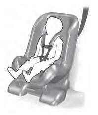
Use a child restraint (sometimes called an
infant carrier, convertible seat, or toddler
seat) for infants, toddlers and children
weighing 40 lb (18 kg) or less (generally
four-years-old or younger).
Using Lap and Shoulder Belts
WARNING: Do not place a rearward
facing child restraint in front of an active
airbag. Failure to follow this instruction
could result in personal injury or death.
read more