Lincoln Aviator: Supplemental Restraint System / Removal and Installation - Front Door Side Impact Sensor
Removal
.jpg) WARNING:
The following procedure prescribes critical repair steps
required for correct restraint system operation during a crash. Follow
all notes and steps carefully. Failure to follow step instructions may
result in incorrect operation of the restraint system and increases the
risk of serious personal injury or death in a crash.
WARNING:
The following procedure prescribes critical repair steps
required for correct restraint system operation during a crash. Follow
all notes and steps carefully. Failure to follow step instructions may
result in incorrect operation of the restraint system and increases the
risk of serious personal injury or death in a crash.
NOTE: LH (left hand) side shown, RH (right hand) side similar.
NOTE: Removal steps in this procedure may contain installation details.
-
Refer to: Pyrotechnic Device Health and Safety Precautions (100-00 General Information, Description and Operation)..jpg) WARNING:
Before beginning any service procedure in this
manual, refer to health and safety warnings in section 100-00 General
Information. Failure to follow this instruction may result in serious
personal injury.
WARNING:
Before beginning any service procedure in this
manual, refer to health and safety warnings in section 100-00 General
Information. Failure to follow this instruction may result in serious
personal injury.
-
Depower the SRS.
Refer to: Supplemental Restraint System (SRS) Depowering (501-20B Supplemental Restraint System, General Procedures).
-
Remove the front door trim panel.
Refer to: Front Door Trim Panel (501-05 Interior Trim and Ornamentation, Removal and Installation).
-
Remove the front door side impact sensor.
-
Disconnect the electrical connector.
-
Remove the bolts.
Torque: 22 lb.in (2.5 Nm)
-
Remove the front door side impact sensor.
-
Disconnect the electrical connector.
.jpg) |
Installation
-
NOTE: The front door side impact sensor mating surfaces must be smooth and allow for a flush attachment to each other.
To install, reverse the removal procedure.
-
Repower the SRS.
Refer to: Supplemental Restraint System (SRS) Repowering (501-20B Supplemental Restraint System, General Procedures).
 Removal and Installation - Driver Knee Airbag
Removal
WARNING:
The following procedure prescribes critical repair steps
required for correct restraint system operation during a crash. Follow
all notes and steps carefully...
 Removal and Installation - Front Impact Severity Sensor
Removal
WARNING:
The following procedure prescribes critical repair steps
required for correct restraint system operation during a crash. Follow
all notes and steps carefully...
Other information:
Lincoln Aviator 2020-2024 Service Manual: Removal and Installation - Front Door Glass Top Run
Removal NOTE: LH (left-hand) side shown, RH (right-hand) side similar. NOTE: Removal steps in this procedure may contain installation details. Remove the front door window glass. Refer to: Front Door Window Glass (501-11 Glass, Frames and Mechanisms, Removal and Installation)...
Lincoln Aviator 2020-2024 Service Manual: General Procedures - Charge Air Cooler (CAC) Cleaning
Cleaning Remove the Turbocharger Boost Pressure (TCBP) sensor from the CAC. Refer to: Turbocharger Boost Pressure (TCBP) and Charger Air Cooler Temperature (CACT) Sensor (303-14A Electronic Engine Controls - 3.0L EcoBoost/3.0L EcoBoost – Hybrid (BQ), Removal and Installation)...
Categories
- Manuals Home
- Lincoln Aviator Owners Manual
- Lincoln Aviator Service Manual
- Child Safety Locks
- Garage Door Opener
- Opening and Closing the Hood
- New on site
- Most important about car
Children and Airbags
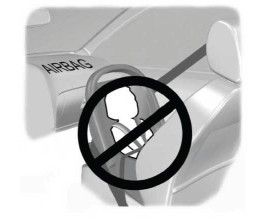
WARNING: Airbags can kill or injure a child in a child restraint. Never place a rear-facing child restraint in front of an active airbag. If you must use a forward-facing child restraint in the front seat, move the seat upon which the child restraint is installed all the way back.

