Lincoln Aviator: Front Seats / Removal and Installation - Driver Multi-Contour Seat Module [SCMG]
Removal
NOTE: Removal steps in this procedure may contain installation details.
NOTE: Drivers seat SCMG (driver multi-contour seat module) shown, passenger seat SCMH (passenger multi-contour seat module) similar.
-
NOTE: This step is only necessary when installing a new component.
NOTE: The PMI (programmable module installation) process must begin with the current SCMG (driver multi-contour seat module) or SCMH (passenger multi-contour seat module) installed. If the current SCMG (driver multi-contour seat module) or SCMH (passenger multi-contour seat module) does not respond to the diagnostic scan tool, the tool may prompt for As-Built Data as part of the repair.
Using a diagnostic scan tool, begin the PMI process for the SCMG or SCMH following the on-screen instructions.
-
Remove the front seat.
Refer to: Front Seat (501-10A Front Seats, Removal and Installation).
-
Remove the front seat backrest panel.
Refer to: Front Seat Backrest Panel (501-10A Front Seats, Removal and Installation).
-
NOTE: After disconnecting the hose and lock assemblies, verify the black O-ring and white spacer remains with each hose.
NOTE: When connecting the hose and lock assemblies, an audible click must be heard for correct installation.
Release the locking tabs and disconnect the hose and lock assemblies from the SCMG and position aside.
.jpg) |
-
Remove the SCMG.
-
Disconnect the electrical connector.
-
Lift upwards on the SCMG to release the rear locking clip.
-
Rotate the SCMG to release the side locking clips.
-
Disconnect the electrical connector.
.jpg) |
Installation
-
To install, reverse the removal procedure.
-
NOTE: This step is only necessary when installing a new component.
Using a diagnostic scan tool, complete the PMI process for the SCMG or SCMH following the on-screen instructions.
 Removal and Installation - Driver Front Seat Module (DSM)
Removal
NOTE:
DSM (driver front seat module) shown, SCMB (front passenger seat control module) is similar.
NOTE:
Removal steps in this procedure may contain installation details...
 Removal and Installation - Front Head Restraint
Removal
NOTE:
This procedure is for vehicles equipped with power head restraint only.
NOTE:
Drivers seat shown, passenger seat similar.
Remove the front seat...
Other information:
Lincoln Aviator 2020-2024 Owners Manual: Using Cross Traffic Alert
The system detects vehicles that approach at a speed between 4 mph (6 km/h) and 37 mph (60 km/h). Coverage decreases when the sensors are partially, mostly or fully obstructed. Slowly reversing helps increase the coverage area and effectiveness. The system turns on when you start the engine and you shift into reverse (R)...
Lincoln Aviator 2020-2024 Service Manual: Removal and Installation - Cellular Antenna Cable
Removal NOTE: Removal steps in this procedure may contain installation details. All vehicles Lower the headliner. Refer to: Headliner - Lowering (501-05 Interior Trim and Ornamentation, Removal and Installation). Remove the LH loadspace trim panel...
Categories
- Manuals Home
- Lincoln Aviator Owners Manual
- Lincoln Aviator Service Manual
- USB Port and Power Point Locations
- Interior Lamps
- Description and Operation - Jacking and Lifting
- New on site
- Most important about car
Remote Control
Passive Key

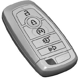
The passive key operates the power locks and the remote start system. The passive key must be in your vehicle to use the push button start.
Note: You may not be able to shift out of park (P) unless the passive key is inside your vehicle.
