Lincoln Aviator 2020-2026 Service Manual / Body and Paint / Body and Paint / Body Closures / Removal and Installation - Fuel Filler Door Spring
Lincoln Aviator: Body Closures / Removal and Installation - Fuel Filler Door Spring
Removal
NOTE: Removal steps in this procedure may contain installation details.
-
Remove the fuel filler door assembly.
Refer to: Fuel Filler Door Assembly (501-03 Body Closures, Removal and Installation).
-
Remove the fuel filler door spring.
-
Press the tab upwards to release the fuel filler door spring from the fuel filler door assembly.
-
Pull and remove the fuel filler door spring.
-
Press the tab upwards to release the fuel filler door spring from the fuel filler door assembly.
.jpg) |
Installation
-
To install, reverse the removal procedure.
 Removal and Installation - Fuel Filler Door Assembly - Plug-In Hybrid Electric Vehicle (PHEV)
Special Tool(s) /
General Equipment
Flat Headed Screw Driver
Knife
Removal
NOTE:
Removal steps in this procedure may contain installation details...
 Removal and Installation - Hands-Free Liftgate Actuation Lower Sensor
Removal
NOTE:
Removal steps in this procedure may contain installation details.
Remove the rear bumper cover.
Refer to: Rear Bumper Cover (501-19 Bumpers, Removal and Installation)...
Other information:
Lincoln Aviator 2020-2026 Owners Manual: SYNC
Argentina Brazil China Djibouti European Union EU Ghana Jamaica Malaysia Mauritania Moldova Morocco Pakistan Paraguay NR: 2017-12-I-0000413 Serbia Singapore South Africa South Korea MSIP-CMM-pAs-FA-170-BCAR-HS Taiwan Ukraine United Arab Emirates (U...
Lincoln Aviator 2020-2026 Service Manual: Removal and Installation - Rear Heater Core Inlet Line
Removal NOTE: The rear heater core inlet line is installed from the factory as a one-piece assembly. The replacement part is supplied as an assembly, containing the rear heater core outlet line and the rear evaporator inlet and outlet lines. Remove the rear evaporator rear outlet and inlet line...
Categories
- Manuals Home
- Lincoln Aviator Owners Manual
- Lincoln Aviator Service Manual
- Resetting the System
- Fuel Quality
- Body and Paint
- New on site
- Most important about car
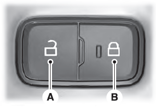
Locking and Unlocking the Doors from Inside

Locking the Doors
Press the lock switch on the door interior trim panel. The doors can no longer be released using the exterior door handle switches and the luggage compartment locks.
Copyright © 2026 www.liaviator2.com
