Lincoln Aviator: Body Closures / Removal and Installation - Rear Gate Trunk Module (RGTM)
Special Tool(s) / General Equipment
| Interior Trim Remover |
Removal
NOTE: Removal steps in this procedure may contain installation details.
-
NOTE: This step is only necessary when installing a new component.
NOTE: The PMI process must begin with the current RGTM installed. If the current RGTM does not respond to the diagnostic scan tool, the tool may prompt for As-Built Data as part of the repair. Using a diagnostic scan tool, begin the PMI process for the RGTM following the on-screen instructions.
Remove the luggage compartment floor covering.
.jpg) |
-
Remove the luggage compartment spare tire cover.
.jpg) |
-
Position the liftgate opening weatherstrip aside.
.jpg) |
-
Remove the liftgate scuff plate trim panel.
-
Release the liftgate scuff plate trim panel clips.
Use the General Equipment: Interior Trim Remover
-
Disconnect the keyless entry rear antenna electrical connector.
-
Release the liftgate scuff plate trim panel clips.
.jpg) |
-
Disconnect the electrical connectors and position aside the electrical harness.
.jpg) |
-
Remove the nuts and remove the RGTM.
.jpg) |
Installation
-
To install, reverse the removal procedure.
-
NOTE: This step is only necessary when installing a new component. Using a diagnostic scan tool, complete the PMI process for the RGTM following the on-screen instructions.
Carry-out the power liftgate initialization.
Refer to: Power Liftgate Initialization (501-03 Body Closures, General Procedures).
 Removal and Installation - Rear Door Check Arm
Removal
NOTE:
Removal steps in this procedure may contain installation details.
NOTE:
LH side shown, RH similar.
Open the door.
Remove the check arm bolt...

Other information:
Lincoln Aviator 2020-2026 Service Manual: Diagnosis and Testing - A Clutch
Symptom Chart A Clutch For A clutch operation, REFER to: A Clutch (307-01A Automatic Transmission - 10-Speed Automatic Transmission – 10R60, Description and Operation). A Clutch Condition Possible Sources Action A clutch does not apply SSA mechanically stuck OFF INSTALL a new solenoid...
Lincoln Aviator 2020-2026 Service Manual: Removal and Installation - Rear Heater Core Shutoff Valve (RHSOV)
Special Tool(s) / General Equipment Hose Clamp(s) Hose Clamp Remover/Installer Removal NOTE: Removal steps in this procedure may contain installation details. Drain the cooling system. Refer to: Engine Cooling System Draining, Vacuum Filling and Bleeding (303-03A Engine Cooling - 3...
Categories
- Manuals Home
- Lincoln Aviator Owners Manual
- Lincoln Aviator Service Manual
- Interior Lamps
- Configuring The Head Up Display
- Remove and Reinstall the Battery
- New on site
- Most important about car
Children and Airbags
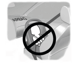
WARNING: Airbags can kill or injure a child in a child restraint. Never place a rear-facing child restraint in front of an active airbag. If you must use a forward-facing child restraint in the front seat, move the seat upon which the child restraint is installed all the way back.