Lincoln Aviator: Roof Opening Panel / Removal and Installation - Roof Opening Panel Motor
Removal
NOTE: Removal steps in this procedure may contain installation details.
-
Lower the headliner.
Refer to: Headliner - Lowering (501-05 Interior Trim and Ornamentation, Removal and Installation).
Roof Opening Panel Motor - Glass
-
NOTE: A new roof opening panel glass motor only moves toward the vent position until initialized.
Remove the roof opening panel glass motor.
-
Disconnect the electrical connector.
-
Remove the retainers and the roof opening glass motor.
Torque: 27 lb.in (3 Nm)
-
Disconnect the electrical connector.
.jpg) |
Roof Opening Panel Motor - Shield
-
NOTE: A new roof opening panel shield motor only moves toward the closed position until initialized.
Remove the roof opening panel shield motor.
-
Disconnect the electrical connector.
-
Remove the retainers and the roof opening panel shield motor.
Torque: 27 lb.in (3 Nm)
-
Disconnect the electrical connector.
.jpg) |
Installation
-
NOTE: When installing the roof opening panel motor, it may be necessary to turn the roof opening panel motor slightly to engage the drive splines.
To install, reverse the removal procedure.
-
Carry out the power roof opening panel initialization.
Refer to: Power Roof Opening Panel Initialization (501-17 Roof Opening Panel, General Procedures).
 Removal and Installation - Roof Opening Panel Glass
Removal
NOTE:
Removal steps in this procedure may contain installation details.
NOTE:
This procedure is for the sliding glass panel only.
Place the roof opening panel shield to the fully OPEN position...
 Removal and Installation - Roof Opening Panel Seal
Removal
Remove the moonroof.
Refer to: Roof Opening Panel Frame (501-17 Roof Opening Panel, Removal and Installation).
To remove the seal, start at the splice joint at center
rear area and pull in the direction shown along the seal path instead of
pulling straight out at 90 degrees...
Other information:
Lincoln Aviator 2020-2026 Owners Manual: Mobile Device Data
If you connect a mobile device to your vehicle, you can display data from your device on the touchscreen for example, music and album art. You can share your vehicle data with mobile apps on your device through the system. The mobile apps function operates by your connected device sending data to us in the United States...
Lincoln Aviator 2020-2026 Service Manual: Description and Operation - Rear Suspension - Component Location
N..
Categories
- Manuals Home
- Lincoln Aviator Owners Manual
- Lincoln Aviator Service Manual
- Description and Operation - Body and Frame
- Anti-Theft Alarm
- Changing the Front Wiper Blades - Vehicles With: Heated Wiper Blades
- New on site
- Most important about car
Activating Intelligent Access
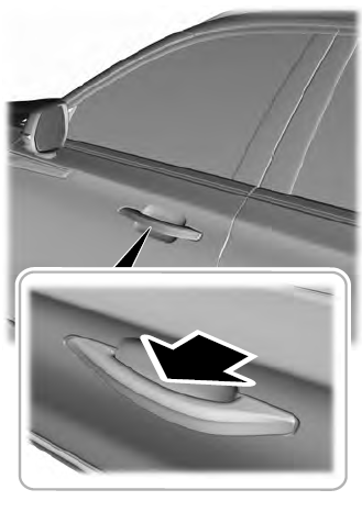
The intelligent access key must be within 3 ft (1 m) of the door or luggage compartment you intend to lock or unlock.
At a Door
Electronic door handles are on each door. Gently depress the switch inside the exterior door handle to unlock and open the door. An unlock symbol illuminates on the door window trim indicating your vehicle is unlocked.

