Lincoln Aviator 2020-2026 Service Manual / Powertrain / Engine / Engine Cooling - 3.0L EcoBoost / Removal and Installation - Thermostat
Lincoln Aviator: Engine Cooling - 3.0L EcoBoost / Removal and Installation - Thermostat
Special Tool(s) / General Equipment
| Hose Clamp Remover/Installer |
Removal
NOTE: Removal steps in this procedure may contain installation details.
-
Drain the cooling system.
Refer to: Engine Cooling System Draining, Vacuum Filling and Bleeding (303-03A Engine Cooling - 3.0L EcoBoost, General Procedures).
-
Remove the air cleaner.
Refer to: Air Cleaner (303-12 Intake Air Distribution and Filtering - 3.0L EcoBoost/3.0L EcoBoost – Hybrid (BQ), Removal and Installation).
-
-
Detach the coolant hose retainers.
-
Release the clamps and disconnect the coolant hoses.
Use the General Equipment: Hose Clamp Remover/Installer
-
Remove the bolt and position the degas bottle aside.
Torque: 44 lb.in (5 Nm)
-
Detach the coolant hose retainers.
.jpg) |
-
NOTICE: Cover the accessory drive belts to prevent coolant contamination of the belts.
Completely cover the accessory drive belts with waterproof plastic.
-
Loosen the clamp and disconnect the upper radiator hose.
Torque: 44 lb.in (5 Nm)
.jpg) |
-
-
Detach the coolant hose retainer.
-
Remove the bolts and the air cleaner support bracket.
Torque: 93 lb.in (10.5 Nm)
-
Detach the coolant hose retainer.
.jpg) |
-
Remove the bolts and disconnect the coolant outlet connector.
Torque: 89 lb.in (10 Nm)
.jpg) |
-
NOTE: The thermostat vent valve should be on top.
NOTE: During installation verify the thermostat vent hole is at the 12 o'clock position.
Remove the thermostat. Inspect the O-ring seal and replace it if necessary.
.jpg) |
Installation
-
Install a new O-ring seal and lubricate it with clean engine coolant.
Refer to: Specifications (303-03A Engine Cooling - 3.0L EcoBoost, Specifications).
-
To install, reverse the removal procedure.
-
Fill and bleed the cooling system.
Refer to: Engine Cooling System Draining, Vacuum Filling and Bleeding (303-03A Engine Cooling - 3.0L EcoBoost, General Procedures).
 Removal and Installation - Radiator
Removal
NOTE:
Removal steps in this procedure may contain installation details.
Remove the cooling module.
Refer to: Cooling Module (303-03A Engine Cooling - 3...
 Removal and Installation - Transmission Fluid Heater Coolant Control Valve
Special Tool(s) /
General Equipment
Hose Clamp Remover/Installer
Removal
WARNING:
When releasing the cooling system pressure, cover the coolant expansion tank cap with a thick cloth...
Other information:
Lincoln Aviator 2020-2026 Owners Manual: Seatbelt Warning Lamp and Indicator Chime
..
Lincoln Aviator 2020-2026 Service Manual: Removal and Installation - Fender Apron Panel
Special Tool(s) / General Equipment 6.5 mm Drill Bit Resistance Spotwelding Equipment Rivet Gun Self-Piercing Rivet (SPR) Remover/Installer Belt Sander Torx Bit Socket Hot Air Gun MIG/MAG Welding Equipment Spot Weld Drill Bit Locking Pliers Materials Name Specification Metal Bonding AdhesiveTA-1, TA-1-B, 3M™ 08115, LORD Fusor® 108B - Seam SealerTA-2-B, 3M™ 08308, LORD Fusor® 803DTM - Removal WARNING: Electric vehicles damaged by a crash may have compromised high voltage safety systems and present a potential high voltage electrical shock hazard...
Categories
- Manuals Home
- Lincoln Aviator Owners Manual
- Lincoln Aviator Service Manual
- Tire Change Procedure
- Fuel Quality
- Configuring The Head Up Display
- New on site
- Most important about car
Child Safety Locks
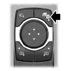
When the child safety locks are set, you cannot open the rear doors from the inside.

The child safety lock control is on the driver door.
Press the control to switch the child safety locks on. Press the control again to switch them off. A light on the child safety control illuminates when you switch them on.
Copyright © 2026 www.liaviator2.com
