Lincoln Aviator: Starting and Stopping the Engine / Starting a Hybrid Electric Vehicle System
Before starting your vehicle, check the following:
- Make sure all occupants fasten their seatbelt.
- Make sure the headlamps and electrical accessories are off.
- Make sure the parking brake is on.
- Put the transmission in park (P).
Note: Do not touch the accelerator pedal.
- Fully press the brake pedal.
- Press the push button ignition switch.
Note: The green ready indicator illuminates letting you know that your vehicle is ready for driving. Since your vehicle comes with a silent key start, the engine may not start when your vehicle starts.
When the engine starts for the first time on your drive, the idle speed increases, this helps to warm up the engine. If the engine idle speed does not slow down automatically, have your vehicle checked by an authorized dealer.
The system does not function if:
- The passive key frequencies are jammed.
- The key battery has no charge.
If you are unable to start your vehicle, do the following:
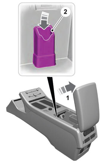
- Open the floor console storage compartment lid.
- Insert the passive key into the backup slot.
- With the key in this position, press the brake pedal then press the push button ignition switch to switch the ignition on and start your vehicle.
- Fast Restart. Vehicles Using Phone as a Key
- Phone as a Key Backup Starting Passcode
- Automatic Engine Shutdown. Automatic Engine Shutdown Override
- Switching Off Your Vehicle When It Is Stationary
- Switching Off Your Vehicle When It Is Moving
- Guarding Against Exhaust Fumes. Important Ventilating Information
 Guarding Against Exhaust Fumes. Important Ventilating Information
Guarding Against Exhaust Fumes
WARNING: Exhaust leaks may result
in entry of harmful and potentially lethal
fumes into the passenger compartment. If
you smell exhaust fumes inside your
vehicle, have your vehicle inspected
immediately...
 Fast Restart. Vehicles Using Phone as a Key
Fast Restart
The fast restart feature allows you to restart
your vehicle within 20 seconds of switching
it off, even if it does not detect a valid
passive key...
Other information:
Lincoln Aviator 2020-2026 Service Manual: Diagnosis and Testing - Instrumentation, Message Center and Warning Chimes
Diagnostic Trouble Code (DTC) Chart Diagnostics in this manual assume a certain skill level and knowledge of Ford-specific diagnostic practices. REFER to: Diagnostic Methods (100-00 General Information, Description and Operation). Diagnostic Trouble Code Chart Module DTC Description Action ABS C0049:01 Brake Fluid Level:General Electrical Failure GO to Pinpoint Test L ABS C0049:7B Brake Fluid Level:Low Fluid Level GO to Pinpoint Test L IPC P0460:11 Fuel Level Sensor "A" Circuit:Circuit Short To Ground GO to Pinpoint Test D IPC P0460:13 Fuel Level Sensor "A" Circuit:Circuit Open GO to Pinpoint Test D IPC U0100:00 Lost Communication With ECM/PCM "A":No Sub Type Information GO to Pinpoint Test CC IPC U0103:00 Lost Communication With Gear Shift Control Module A:No Sub Type Information GO to Pinpoint Test CE IPC U0111:00 Lost Communication With Battery Energy Control Module "A":No Sub Type Information GO to Pinpoint Test CF IPC U0121:00 Lost Communication With Anti-Lock Brake System (ABS) Control Module: No Sub Type Information GO to Pinpoint Test CG IPC U013F:00 Lost Communication With Pedestrian Alert Control Module:No Sub Type Information GO to Pinpoint Test CI IPC U0140:00 Lost Communication With Body Control Module: No Sub Type Information GO to Pinpoint Test CJ IPC U0151:00 Lost Communication With Restraints Control Module: No Sub Type Information GO to Pinpoint Test CM IPC U0158:00 Lost Communication With Head Up Display:No Sub Type Information GO to Pinpoint Test CN IPC U0159:00 Lost Communication With Parking Assist Control Module "A": No Sub Type Information GO to Pinpoint Test CP IPC U0193:00 Lost Communication With "Digital Audio Control Module A": No Sub Type Information GO to Pinpoint Test CQ IPC U0199:00 Lost Communication With "Door Control Module A":No Sub Type Information GO to Pinpoint Test CR IPC U0212:00 Lost Communication With Steering Column Control Module: No Sub Type Information GO to Pinpoint Test CS IPC U0212:82 Lost Communication With Steering Column Control Module:Alive/Sequence Counter Incorrect/Not Updated GO to Pinpoint Test CS IPC U0232:00 Lost Communication With Side Obstacle Detection Control Module - Left: No Sub Type Information GO to Pinpoint Test CU IPC U0233:00 Lost Communication With Side Obstacle Detection Control Module - Right: No Sub Type Information GO to Pinpoint Test CU IPC U023A:00 Lost Communication With Image Processing Module A: No Sub Type Information GO to Pinpoint Test CW IPC U023B:82 Lost Communication With Image Processing Module B:Alive/Sequence Counter Incorrect/Not Updated GO to Pinpoint Test CX IPC U0241:00 Lost Communication With Headlamp Control Module "A":No Sub Type Information GO to Pinpoint Test CY IPC U0253:00 Lost Communication With Accessory Protocol Interface Module:No Sub Type Information GO to Pinpoint Test CZ IPC U0260:00 Lost Communication With Seat Control Switch Module "A":No Sub Type Information GO to Pinpoint Test DA IPC U0293:00 Lost Communication with Hybrid/EV Powertrain Control Module:No Sub Type Information GO to Pinpoint Test CD IPC U0293:82 Lost Communication with Hybrid/EV Powertrain Control Module:Alive/Sequence Counter Incorrect/Not Updated GO to Pinpoint Test CD IPC U0401:00 Invalid Data Received from ECM/PCM A:No Sub Type Information GO to Pinpoint Test CC IPC U0401:81 Invalid Data Received from ECM/PCM A:Invalid Serial Data Received GO to Pinpoint Test CC IPC U0401:82 Invalid Data Received from ECM/PCM A:Alive/Sequence Counter Incorrect/Not Updated GO to Pinpoint Test CC IPC U0401:86 Invalid Data Received from ECM/PCM A:Signal Invalid GO to Pinpoint Test CC IPC U0405:56 Invalid Data Received From Cruise Control Module:Invalid/Incompatible Configuration GO to Pinpoint Test CK IPC U0412:86 Invalid Data Received From Battery Energy Control Module "A":Signal Invalid GO to Pinpoint Test CF IPC U0415:00 Invalid Data Received From Anti-Lock Brake System (ABS) Module: No Sub Type Information GO to Pinpoint Test CG IPC U0415:82 Invalid Data Received from Anti-Lock Brake System (ABS) Control Module "A":Alive/Sequence Counter Incorrect/Not Updated GO to Pinpoint Test CG IPC U0420:82 Invalid Data Received from Power Steering Control Module "A":Alive/Sequence Counter Incorrect/Not Updated GO to Pinpoint Test CH IPC U0422:00 Invalid Data Received From Body Control Module:No Sub Type Information GO to Pinpoint Test CJ IPC U0424:80 Invalid Data Received From HVAC Control Module:ISO/SAE Reserved GO to Pinpoint Test CL IPC U0424:81 Invalid Data Received From HVAC Control Module:Invalid Serial Data Received GO to Pinpoint Test CL IPC U0424:82 Invalid Data Received From HVAC Control Module:Alive/Sequence Counter Incorrect/Not Updated GO to Pinpoint Test CL IPC U0431:82 Invalid Data Received From Body Control Module "A":Alive/Sequence Counter Incorrect/Not Updated GO to Pinpoint Test CJ IPC U0452:81 Invalid Data Received From Restraints Control Module:Invalid Serial Data Received GO to Pinpoint Test CM IPC U045A:82 Invalid Data Received From Parking Assist Control Module "A":Alive/Sequence Counter Incorrect/Not Updated GO to Pinpoint Test CP IPC U049C:82 Invalid Data Received From Battery Charger Control Module "A":Alive/Sequence Counter Incorrect/Not Updated GO to Pinpoint Test CO IPC U0531:82 Invalid Data Received From Rear Gate Module:Alive/Sequence Counter Incorrect/Not Updated GO to Pinpoint Test CT IPC U0533:00 Invalid Data Received From Side Obstacle Detection Control Module-Left: No Sub Type information GO to Pinpoint Test CU IPC U0533:56 Invalid Data Received From Side Obstacle Detection Control Module "A":Invalid/Incompatible Configuration GO to Pinpoint Test CV IPC U0534:00 Invalid Data Received From Side Obstacle Detection Control Module-Right: No Sub Type Information GO to Pinpoint Test CU IPC U0534:56 Invalid Data Received From Side Obstacle Detection Control Module "B":Invalid/Incompatible Configuration GO to Pinpoint Test CV IPC U0542:82 Invalid Data Received From Headlamp Control Module "A":Alive/Sequence Counter Incorrect/Not Updated GO to Pinpoint Test CY IPC U0594:86 Invalid Data Received From Hybrid/EV Powertrain Control Module:Signal Invalid GO to Pinpoint Test CD IPC U2100:00 Initial Configuration Not Complete:No Sub Type Information GO to Pinpoint Test DB IPC U3000:04 Control Module:System Internal Failures GO to Pinpoint Test DC IPC U3000:46 Control Module:Calibration/Parameter Memory Failure GO to Pinpoint Test DC IPC U3003:16 Battery Voltage: Circuit Voltage Below Threshold GO to Pinpoint Test DE IPC U3003:17 Battery Voltage: Circuit Voltage Above Threshold GO to Pinpoint Test DF IPC U300A:64 Ignition Switch:Signal Plausibility Failure GO to Pinpoint Test DD PCM P0461:00 Fuel Level Sensor "A" Circuit Range/Performance:No Sub Type Information GO to Pinpoint Test D PCM P0462:00 Fuel Level Sensor "A" Circuit Low:No Sub Type Information GO to Pinpoint Test D PCM P0463:00 Fuel Level Sensor "A" Circuit High:No Sub Type Information GO to Pinpoint Test D PCM P0522:00 Engine Oil Pressure Sensor/Switch "A" Circuit Low:No Sub Type Information GO to Pinpoint Test W PCM P0523:00 Engine Oil Pressure Sensor/Switch "A" Circuit High:No Sub Type Information GO to Pinpoint Test W PCM P25B0:00 Fuel Level Sensor "A" Stuck:No Sub Type Information GO to Pinpoint Test D SIMA B1380:4A Steering Wheel Right Switch Pack:Incorrect Component Installed GO to Pinpoint Test AG SIMA B1380:71 Steering Wheel Right Switch Pack:Actuator Stuck GO to Pinpoint Test AG Symptom Chart(s) Symptom Chart: Instrument Panel Cluster (IPC) Diagnostics in this manual assume a certain skill level and knowledge of Ford-specific diagnostic practices...
Lincoln Aviator 2020-2026 Service Manual: Diagnosis and Testing - Fog Lamps
Diagnostic Trouble Code (DTC) Chart Diagnostics in this manual assume a certain skill level and knowledge of Ford-specific diagnostic practices. REFER to: Diagnostic Methods (100-00 General Information, Description and Operation). Diagnostic Trouble Code Chart Module DTC Description Action BCM B1147:11 Left Front Fog Lamps:Circuit Short To Ground GO to Pinpoint Test B BCM B1147:15 Left Front Fog Lamps:Circuit Short To Battery or Open GO to Pinpoint Test B BCM B1148:11 Right Front Fog Lamps:Circuit Short To Ground GO to Pinpoint Test B BCM B1148:15 Right Front Fog Lamps:Circuit Short To Battery or Open GO to Pinpoint Test B BCM B1499:11 Exterior Lamps Power Supply "A":Circuit Short To Ground GO to Pinpoint Test B BCM B1499:15 Exterior Lamps Power Supply "A":Circuit Short To Battery or Open GO to Pinpoint Test B BCM B149D:11 Exterior Lamps Power Supply "B":Circuit Short To Ground GO to Pinpoint Test B BCM B149D:15 Exterior Lamps Power Supply "B":Circuit Short To Battery or Open GO to Pinpoint Test B BCM B1A79:11 Rear Fog Lamp:Circuit Short To Ground GO to Pinpoint Test C BCM B1A79:15 Rear Fog Lamp:Circuit Short To Battery or Open GO to Pinpoint Test C Symptom Chart Symptom Chart: Fog Lamps Diagnostics in this manual assume a certain skill level and knowledge of Ford-specific diagnostic practices...
Categories
- Manuals Home
- Lincoln Aviator Owners Manual
- Lincoln Aviator Service Manual
- Configuring The Head Up Display
- Opening and Closing the Hood
- Garage Door Opener
- New on site
- Most important about car
Children and Airbags
WARNING: Airbags can kill or injure a child in a child restraint. Never place a rear-facing child restraint in front of an active airbag. If you must use a forward-facing child restraint in the front seat, move the seat upon which the child restraint is installed all the way back.
