Lincoln Aviator: Fuel System - General Information - 3.0L EcoBoost / General Procedures - Fuel System Pressure Check
Special Tool(s) / General Equipment
.jpg) |
310-D009
(D95L-7211-A)
Fuel Pressure Test Kit |
Check
NOTE: This Fuel System Pressure Check is for the low pressure side of the system.
-
Release the fuel system pressure.
Refer to: Fuel System Pressure Release (310-00A Fuel System - General Information - 3.0L EcoBoost, General Procedures).
-
Disconnect the battery ground cable.
Refer to: Battery Disconnect and Connect (414-01 Battery, Mounting and Cables, General Procedures).
-
-
Remove the nuts.
Torque: 18 lb.ft (25 Nm)
-
Remove the bolt and High pressure pump shield.
Torque: 18 lb.ft (25 Nm)
-
Remove the nuts.
.jpg) |
-
Disconnect the fuel supply tube quick connect coupling.
.jpg) |
-
Install the Fuel Pressure Test Adapter and the Fuel
Pressure Test Kit between the fuel tube and the fuel jumper tube.
Use Special Service Tool: 310-D009 (D95L-7211-A) Fuel Pressure Test Kit.
.jpg) |
-
NOTE: The fuel pump control module electrical connector was previously disconnected to release the fuel system pressure and must be reconnected to test the fuel system pressure.
Reconnect the fuel pump control module electrical connector.
-
Reconnect the battery ground cable.
Refer to: Battery Disconnect and Connect (414-01 Battery, Mounting and Cables, General Procedures).
-
NOTE: Carry out a Key ON Engine OFF (KOEO) visual inspection for fuel leaks prior to completing the fuel system pressure test.
NOTE: After completion of the fuel system pressure test, open the drain valve on the Fuel Pressure Test Kit and release any residual fuel into a suitable container prior to removing the tool.
Test the fuel system pressure to make sure it is within the specified range.
Refer to: Specifications (310-00A Fuel System - General Information - 3.0L EcoBoost, Specifications).
 Diagnosis and Testing - Fuel System - 3.0L EcoBoost
Symptom Chart(s)
Symptom Chart: Fuel System
Diagnostics in this manual assume a certain skill level and knowledge of Ford-specific diagnostic practices...
 General Procedures - Fuel Tank Draining
Special Tool(s) /
General Equipment
292-00004Fuel Tanker 100 GPM
Draining
WARNING:
Before beginning any service procedure in this
section, refer to Safety Warnings in section 100-00 General Information...
Other information:
Lincoln Aviator 2020-2026 Owners Manual: Replacing the Cabin Air Filter
Replace the filter at regular intervals. The cabin air filter is behind the glove compartment. To remove the lower glove compartment and access the filter: Open the glove compartment. Press the tab on each side. Fully lower the glove compartment...
Lincoln Aviator 2020-2026 Owners Manual: System Errors. Switching the System On and Off
System Errors If the system detects a fault, a warning lamp illuminates and a message displays. Switching the System On and Off You can switch the blind spot information system with trailer tow off by not selecting a trailer the information display...
Categories
- Manuals Home
- Lincoln Aviator Owners Manual
- Lincoln Aviator Service Manual
- Opening and Closing the Hood
- Configuring The Head Up Display
- Body and Paint
- New on site
- Most important about car
Activating Intelligent Access
The intelligent access key must be within 3 ft (1 m) of the door or luggage compartment you intend to lock or unlock.
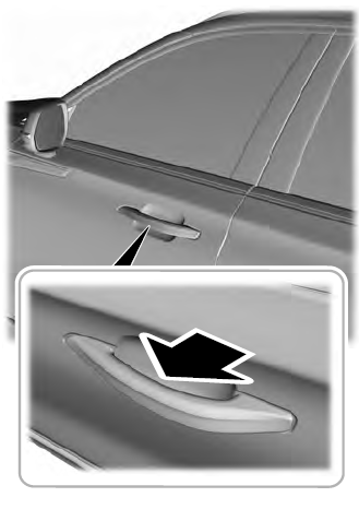
At a Door
Electronic door handles are on each door. Gently depress the switch inside the exterior door handle to unlock and open the door. An unlock symbol illuminates on the door window trim indicating your vehicle is unlocked.

