Lincoln Aviator 2020-2026 Service Manual / Body and Paint / Body and Paint / Wipers and Washers / General Procedures - Washer Hose Repair
Lincoln Aviator: Wipers and Washers / General Procedures - Washer Hose Repair
Repair
NOTE: This procedure may be carried out on rubber hoses only. If a plastic washer hose is damaged, a new washer hose must be installed.
-
Locate and verify the damaged washer hose.
-
Cut the hose cleanly and remove the damaged portion of the washer hose.
Dimension: 0.5000 in ( 12.7 mm)
.jpg) |
-
Install a windshield washer hose adapter between the cut ends of the hose.
.jpg) |
-
NOTE: In difficult cases, clamping may be required.
If necessary, install a segment of 6.4 mm (0.25 in) ID black rubber hose over the ends of the washer hose and clamp both ends of the rubber hose using spring clamps.
 General Procedures - Washer Hose Coupling
Disconnect
WARNING:
Before beginning any service procedure in this
section, refer to Safety Warnings in section 100-00 General Information...
 Removal and Installation - Front Parking Aid Camera Washer Jet
Removal
NOTE:
Removal steps in this procedure may contain installation details.
Remove the front parking aid camera.
Refer to: Front Parking Aid Camera (413-13B Parking Aid - Vehicles With: Parking Aid Camera, Removal and Installation)...
Other information:
Lincoln Aviator 2020-2026 Service Manual: Removal and Installation - Valve Cover LH
Special Tool(s) / General Equipment 205-153 (T80T-4000-W) Handle 303-1247VCT Spark Plug Tube Seal Remover and InstallerTKIT-2006UF-FLMTKIT-2006UF-ROW Materials Name Specification Motorcraft® High Performance Engine RTV SiliconeTA-357 WSE-M4G323-A6 Removal NOTICE: During engine repair procedures, cleanliness is extremely important...
Lincoln Aviator 2020-2026 Owners Manual: Manual Zoom
WARNING: When manual zoom is on, the full area behind your vehicle may not show. Be aware of your surroundings when using the manual zoom feature. Note: Manual zoom is only available when the transmission is in reverse (R). Note: When you enable manual zoom, only the centerline is shown...
Categories
- Manuals Home
- Lincoln Aviator Owners Manual
- Lincoln Aviator Service Manual
- USB Port and Power Point Locations
- Resetting the System
- Remove and Reinstall the Battery
- New on site
- Most important about car
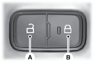
Locking and Unlocking the Doors from Inside

Locking the Doors
Press the lock switch on the door interior trim panel. The doors can no longer be released using the exterior door handle switches and the luggage compartment locks.
Copyright © 2026 www.liaviator2.com
