
Lincoln Aviator 2020-2026 Owners Manual / Instrument Cluster
Lincoln Aviator: Instrument Cluster
 Moonroof (If Equipped)
WARNING: Do not leave children
unattended in your vehicle and do not let
them play with the moonroof. Failure to
follow this instruction could result in
personal injury...
 Gauges
Note: Clusters shown in single gauge view.
Note: Displays may appear slightly different
depending on region.
Status Bar.
Speedometer.
Information on demand...
Other information:
Lincoln Aviator 2020-2026 Owners Manual: Rear Occupant Alert System Precautions and Limitations
Rear Occupant Alert System Precautions WARNING: On hot days, the temperature inside the vehicle can rise very quickly. Exposure of people or animals to these high temperatures for even a short time can cause death or serious heat related injuries, including brain damage...
Lincoln Aviator 2020-2026 Owners Manual: SiriusXM® Satellite Radio (If Activated)
Note: This feature may not be available in all markets and requires an active subscription. SiriusXM satellite radio is a subscription-based satellite radio service that broadcasts a variety of music, sports, news, weather, traffic and entertainment programming...
Categories
- Manuals Home
- Lincoln Aviator Owners Manual
- Lincoln Aviator Service Manual
- Remove and Reinstall the Battery
- Opening and Closing the Hood
- Keyless Entry
- New on site
- Most important about car
Locking and Unlocking the Doors from Inside
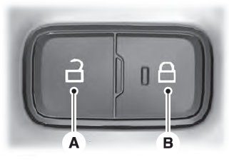
Locking the Doors
Press the lock switch on the door interior trim panel. The doors can no longer be released using the exterior door handle switches and the luggage compartment locks.

Copyright © 2026 www.liaviator2.com