Lincoln Aviator: Exterior Trim and Ornamentation / Removal and Installation - Front Door Upper Moulding
Removal
NOTE: Removal steps in this procedure may contain installation details.
NOTE: LH side shown, RH similar.
All vehicles
-
Remove the upper belt moulding screw at front of the door.
.jpg) |
-
position the screw cap aside and remove the upper belt moulding screw at rear of the door.
.jpg) |
-
Using a non-marring trim tool, disengage the moulding from the channel in the door and remove the moulding.
.jpg) |
-
Position the glass run weatherstrip aside.
.jpg) |
-
Remove the screw on the upper door frame.
.jpg) |
Vehicles With: Keyless Vehicle System
-
Remove the LHF door window regulator and motor.
Refer to: Front Door Window Regulator and Motor (501-11 Glass, Frames and Mechanisms, Removal and Installation).
-
Disconnect the electrical connector.
.jpg) |
All vehicles
-
NOTE: Standard front door upper moulding shown, keyless entry similar.
-
Remove the retainer clips and dislodge the 4way clip.
-
Remove the front door upper moulding.
-
Remove the retainer clips and dislodge the 4way clip.
.jpg) |
-
NOTE: The keypad actuator can be serviced separately from the moulding if required.
Remove the screws and detach the retainer clip.
Torque: 8 lb.in (0.9 Nm)
.jpg) |
Installation
All vehicles
-
-
Install the 4way clip and the retainers
-
Install the front door upper moulding.
-
Install the 4way clip and the retainers
.jpg) |
Vehicles With: Keyless Vehicle System
-
Connect the electrical connector.
.jpg) |
-
Install the LHF door window regulator and motor.
Refer to: Front Door Window Regulator and Motor (501-11 Glass, Frames and Mechanisms, Removal and Installation).
All vehicles
-
Install the screw on the upper door frame.
Torque: 12 lb.in (1.3 Nm)
.jpg) |
-
Reposition the glass run weatherstrip.
.jpg) |
-
Install the upper belt moulding.
.jpg) |
-
Install the upper belt moulding screw at rear of the door and install the screw cap.
Torque: 12 lb.in (1.3 Nm)
.jpg) |
-
Install the upper belt moulding screw at front of the door.
Torque: 12 lb.in (1.3 Nm)
.jpg) |
 Removal and Installation - Front Door Moulding
Removal
NOTE:
Removal steps in this procedure may contain installation details.
NOTE:
LH door shown, RH door similar.
NOTE:
Do not use excessive force when removing retainers, to avoid damage to moulding...
 Removal and Installation - Front Fender Moulding
Removal
NOTE:
Removal steps in this procedure may contain installation details.
NOTE:
LH side shown, RH side similar.
Remove the screws...
Other information:
Lincoln Aviator 2020-2026 Service Manual: Removal and Installation - Front Driveshaft Slip Yoke Boot
Special Tool(s) / General Equipment Crimping Tool Removal Remove the transfer case. Remove and discard the boot clamp. Remove and discard the front driveshaft boot. Installation NOTE: Make sure that the mating faces are clean and free of foreign material...
Lincoln Aviator 2020-2026 Owners Manual: Gauges
Note: Clusters shown in single gauge view. Note: Displays may appear slightly different depending on region. Status Bar. Speedometer. Information on demand. Vehicle driving range. Fuel and battery gauges. Engine coolant temperature gauge. Tachometer...
Categories
- Manuals Home
- Lincoln Aviator Owners Manual
- Lincoln Aviator Service Manual
- Wireless Accessory Charger (If Equipped)
- Configuring The Head Up Display
- Opening and Closing the Hood
- New on site
- Most important about car
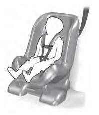
Child Seats

Use a child restraint (sometimes called an infant carrier, convertible seat, or toddler seat) for infants, toddlers and children weighing 40 lb (18 kg) or less (generally four-years-old or younger).
Using Lap and Shoulder Belts
WARNING: Do not place a rearward facing child restraint in front of an active airbag. Failure to follow this instruction could result in personal injury or death.
