Lincoln Aviator: Fuel Tank and Lines - 3.0L EcoBoost / Removal and Installation - Fuel Pump and Sender Unit
Special Tool(s) / General Equipment
.jpg) |
310-123 Locking Ring, Fuel Tank TKIT-2004J-F TKIT-2005U-LM |
Removal
.jpg)
.jpg)
.jpg)
.jpg) WARNING:
Do not smoke, carry lighted tobacco or have an open flame of
any type when working on or near any fuel-related component. Highly
flammable mixtures may be present and may be ignited. Failure to follow
these instructions may result in serious personal injury.
WARNING:
Do not smoke, carry lighted tobacco or have an open flame of
any type when working on or near any fuel-related component. Highly
flammable mixtures may be present and may be ignited. Failure to follow
these instructions may result in serious personal injury.
NOTE: Removal steps in this procedure may contain installation details.
-
With the vehicle in NEUTRAL, position it on a hoist.
Refer to: Jacking and Lifting (100-02 Jacking and Lifting, Description and Operation).
-
Remove the Fuel Tank.
Refer to: Fuel Tank (310-01A Fuel Tank and Lines - 3.0L EcoBoost, Removal and Installation).
-
Remove the bolt and shield.
Torque: 53 lb.in (6 Nm)
.jpg) |
-
NOTE: To avoid introducing contamination into the fuel tank use compressed air to clean the fuel pump and sender unit flange surfaces and the immediate surrounding area of any dirt or foreign material.
Remove the quick connectors, position the hoses aside, then disconnect the electrical connector.
Refer to: Quick Release Coupling (310-00A Fuel System - General Information - 3.0L EcoBoost, General Procedures).
.jpg) |
-
NOTE: Note the position of the fuel pump and sender unit for installation.
Using the special tool remove the lock ring and the fuel pump and sender unit.
Use Special Service Tool: 310-123 Locking Ring, Fuel Tank.
.jpg) |
-
Lift the Fuel Pump and Sender unit slightly and disconnect the vapor line.
Refer to: Quick Release Coupling (310-00A Fuel System - General Information - 3.0L EcoBoost, General Procedures).
.jpg) |
-
NOTICE: Take extra care not to damage the fuel tank level sensor and float arm.
Remove and discard the O-ring.
.jpg) |
Installation
-
NOTICE: Take extra care not to damage the fuel tank level sensor and float arm.
Reconnect the vapor line.
Refer to: Quick Release Coupling (310-00A Fuel System - General Information - 3.0L EcoBoost, General Procedures).
.jpg) |
-
NOTE: Use new O-Ring Seal.
NOTE: Make sure that the seal is correctly located.
.jpg) |
-
NOTE: Make sure that the location marks are aligned.
.jpg) |
-
To install, reverse the removal procedure.
 Removal and Installation - Fuel Lines
Removal
Disconnect the battery.
Refer to: Battery Disconnect and Connect (414-01 Battery, Mounting and Cables, General Procedures).
With the vehicle in NEUTRAL, position it on a hoist...
 Removal and Installation - Fuel Tank Filler Pipe
Removal
NOTE:
Removal steps in this procedure may contain installation steps.
Disconnect the battery.
Refer to: Battery Disconnect and Connect (414-01 Battery, Mounting and Cables, General Procedures)...
Other information:
Lincoln Aviator 2020-2026 Owners Manual: Rear Occupant Alert System Indicators and Audible Warnings
Indicators Message Check rear seats for occupants. Displays when you switch your vehicle off after the alert conditions are met. The message displays for a short period of time. Press Close to acknowledge and remove the message. Audible Warnings Sounds when you switch your vehicle off after the alert conditions are met...
Lincoln Aviator 2020-2026 Service Manual: Removal and Installation - Wiper Linkage Assembly
Removal NOTE: Removal steps in this procedure may contain installation details. NOTE: The hood is removed in this procedure for clarity. Remove the cowl panel grille. Refer to: Cowl Panel Grille (501-02 Front End Body Panels, Removal and Installation)...
Categories
- Manuals Home
- Lincoln Aviator Owners Manual
- Lincoln Aviator Service Manual
- Fuel Quality
- Remove and Reinstall the Battery
- Garage Door Opener
- New on site
- Most important about car
Activating Intelligent Access
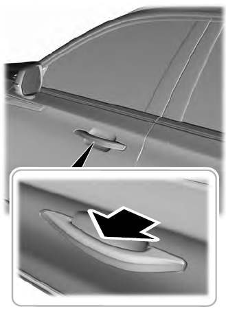
The intelligent access key must be within 3 ft (1 m) of the door or luggage compartment you intend to lock or unlock.
At a Door
Electronic door handles are on each door. Gently depress the switch inside the exterior door handle to unlock and open the door. An unlock symbol illuminates on the door window trim indicating your vehicle is unlocked.

