
Lincoln Aviator 2020-2026 Owners Manual / Roadside Emergencies
Lincoln Aviator: Roadside Emergencies
- Roadside Assistance
- Hazard Flashers
- Fuel Shutoff
- Jump Starting the Vehicle
- Collision, Damage or Fire Event
- Post-Crash Alert System
- Transporting the Vehicle
 Floor Mats
WARNING: Use a floor mat designed
to fit the footwell of your vehicle that does
not obstruct the pedal area. Failure to
follow this instruction could result in the
loss of control of your vehicle, personal
injury or death...
 Roadside Assistance
Vehicles sold in the United States: Getting Roadside Assistance
To fully assist you should you have a vehicle
concern, Lincoln Motor Company offers a
complimentary roadside assistance program...
Other information:
Lincoln Aviator 2020-2026 Service Manual: Removal and Installation - Second Row Single Seat Backrest Cover
Special Tool(s) / General Equipment Interior Trim Remover Removal NOTE: LH (left hand) shown, RH (right hand) similar. Remove the second row seat. Refer to: Second Row Seat (501-10B Second Row Seats, Removal and Installation)...
Lincoln Aviator 2020-2026 Owners Manual: Returning Your Vehicle to Normal Mode
Once it is safe to do so, reconnect the negative, black, battery cable to the battery. Apply the parking brake.Note: If the vehicle battery is dead, you could require an external power source to apply the parking brake. Fully apply the brake pedal and hold, do not release...
Categories
- Manuals Home
- Lincoln Aviator Owners Manual
- Lincoln Aviator Service Manual
- Body and Paint
- Drive Modes
- Resetting the System
- New on site
- Most important about car
Activating Intelligent Access
The intelligent access key must be within 3 ft (1 m) of the door or luggage compartment you intend to lock or unlock.
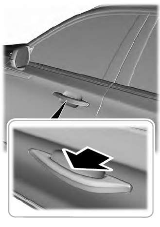
At a Door
Electronic door handles are on each door. Gently depress the switch inside the exterior door handle to unlock and open the door. An unlock symbol illuminates on the door window trim indicating your vehicle is unlocked.

Copyright © 2026 www.liaviator2.com